Using the Roadmap
This roadmap is divided into stages. Each stage is to be done in sequential order. You will build eXpOS incrementally. Links are provided throughout the document for further reference. There are two kinds of links. The contents of the important links must be read immediately before proceeding with the roadmap. The informative links may be clicked for more information about a particular concept. However this information may not be necessary at that point and you may proceed with the roadmap without visiting these links.
It is very important that you proceed with the roadmap on a regular schedule and not get lost in the links. Hence, an approximate amount of time (in hours) which you are expected to spend on each stage is noted along with the stage. If you find that reading a particular documentation/link takes too much time, skip it for the time being and come back to it only when needed.
-
Preparatory Stages:
The preparatory stages help you to get familiarized with the disk bootstrap loading process, disk access mechanism, file-system specification, debugger, paging hardware, interrupt handling mechanism, program loading, library linkage and function calling conventions, application binary interface (ABI), context switching between applications and so forth. You will need 2-3 weeks to complete these stages.

The eXpOS package that you had downloaded in the previous stage consists mainly of a machine simulator. The machine is called the eXperimental String Machine (XSM) and consists of a processor, memory and disk. Some support tools that help you to program the machine are also provided.
One important point to note about the system is that the machine is a bare, and comes with no software in it (except for a boot ROM). Hence, the only way to insert some software code into the system is to prepare the code "outside" (that is, in your Linux/Unix system) and insert your code into the machine. The support tools provided along with the package are precisely designed to help you with this task.
The package comes with three major support tools - two compilers and a disk interface tool called XFS-Interface. The compilers allow you to write high level code and translate it into the XSM machine code. We will look at them in later stages. The XFS-Inteface tool helps you to transfer files between your Linux/Unix system and the XSM machines disk.
XSM machine's disk contains 512 blocks, each capable of storing 512 words. When files are stored in the disk, some format has to be followed so that one can figure out where in the disk are the blocks of a file located.
XSM disk is formatted to what is known as the eXpFS file system format. The format specifies how data as well as meta-data for each file stored in the disk must be organized. The XFS interface tool allows you to load data files (and executable files as well) from your Linux/Unix system into the XSM disk in accordance with the eXpFS format.
The eXpFS format specifies that each data/executable file can span across at most four data blocks, and that the index to these blocks along with the name and the size of the file must be stored in a pre-define area of the disk called the Inode table. (The inode table is stored in disk blocks 3 and 4). There are also other pre-defined areas of the disk that stores meta data about the disk (see description of the root file and the disk free list for more details). When you use XFS interface to load a file from your Linux/Unix system to the XSM disk, the interface tool will correctly fill all the required meta data information as stipulated by the eXpFS format.
The eXperimental Filesystem (eXpFS) is a simulated filesystem. A UNIX file named "disk.xfs" simulates the hard disk of the XSM machine. Building eXpOS begins with understanding the underlying filesystem (eXpFS) and its interface (xfs-interface) to the host (UNIX) environment. The xfs-interface is used for transferring files between your linux system and the xsm disk.

In this stage, you will create a text file and load it to the XFS disk using xfs-interface.
-
Run the XFS Interface
This will take you to the xfs-interface prompt.
cd $HOME/myexpos/xfs-interface
./xfs-interface
-
Start by formatting the disk to the eXpOS file system format in the XFS interface using fdisk
command.
The fdisk command converts the raw disk into the filesystem format recognised by the eXpOS operating system. It initialises the disk data structures such as disk free list, inode table, user table and root file .
Type the following commands in the xfs-interface prompt.# fdisk # exit
You will be back in the UNIX shell and a file named disk.xfs is created in the location $HOME/myexpos/xfs-interface/. This UNIX file simulates the hard disk of the XSM machine. The disk is formatted to eXperimental File System (eXpFS) (see eXpFS Specification).
The XSM machine's disk is a sequence of 512 blocks, each block capable of holding 512 words (see Disk Organization). The second block of the formatted disk contains a disk free list which is explained below. -
The Disk Free List
in XFS is a data structure which keeps track of used and unused blocks in the disk. An unused
block is indicated by 0 and a used block is indicated by 1. Check the contents of the Disk
Free List after formatting the disk. Use the df command to view the Disk Free List
(stored in disk block number 2). The output will be as follows:
The first 69 blocks (blocks 0 to 68) are reserved for stroing various OS data structures and routines as well as Idle code, INIT program, etc (see Disk Organization). Hence the Disk Free List entries for these are marked as 1 (used) and the remaining entries for blocks 69 to 511 are 0 (unused).
0    -   1
1    -   1
2    -   1
3    -   1
4    -   1
5    -   1
6    -   1
7    -   1
8    -   1
9    -   1
10   -   1
11   -   1
12   -   1
13   -   1
14   -   1
15   -   1
16   -   1
17   -   1
18   -   1
19   -   1
20   -   1
21   -   1
22   -   1
23   -   1
24   -   1
25   -   1
.
.
No of Free Blocks = 443
Total No of Blocks = 512
- Create a file in your UNIX machine with sample data. A sample data file is given below:
Save the file as $HOME/myexpos/sample.dat
There is a place where the sidewalk ends
And before the street begins,
And there the grass grows soft and white,
And there the sun burns crimson bright,
And there the moon-bird rests from his flight
To cool in the peppermint wind.
- Load this data file ($HOME/myexpos/sample.dat) to the XFS disk from your UNIX
machine. This can be done by the following commands:
This will take you to the xfs-interface prompt. Type the following commands.
cd $HOME/myexpos/xfs-interface
./xfs-interface
This will load the file to the XFS disk and the following updations happen in disk data structures :# load --data $HOME/myexpos/sample.dat
- A disk block will be allocated for the file (as sample.dat contains less than 512 words) and corresponding to this allocated block (here block 69 - this is because the 1st free block is allocated by the allocator), an entry will be marked as 1 (used) in the Disk Free List.
- An entry in the Inode Table will be created for this file. Inode Table contains information such as the file type, file name, file size, userid, permission and the block numbers of the data blocks of the file. The owner of data files loaded through xfs-interface is the root. Userid is the index of the user entry in the User Table. The userid of root is 1 and hence the userid field in the inode table is set to 1 for all data files loaded through the xfs interface. The permission is set to open(1). Note that any file in eXpFS file system is permitted to have a maximum of four data blocks.
- An entry for this file will be made in the Root File also.
Before proceeding further you must be clear about eXpFS (eXperimental File System). In the following steps we will see the above mentioned updations. - Find out the block numbers of the Data Blocks corresponding to the loaded file. Use the copy
command to copy the Inode Table(Inode Table is stored in disk blocks 3 and 4) to a
UNIX file (say $HOME/myexpos/inode_table.txt).
# copy 3 4 $HOME/myexpos/inode_table.txt
# exit
Note:The Inode table occupies only the first 960 words (60 entries, each of size 16 words) in the disk blocks 3 and 4. User table occupies the next 32 words (16 entries, each of size 2 words) and the last 32 words are reserved for future use. (You will learn about User Table later on).
Now check the Inode table entry for the file sample.dat in the UNIX file inode_table.txt and find the block numbers of its data blocks. The contents of the file inode_table.txt will be as follows:
1 root 512 0 0 -1 -1 -1 5 -1 -1 -1 -1 -1 -1 -1 2 sample.dat 19 1 1 -1 -1 -1 69 -1 -1 -1 -1 -1 -1 -1 -1 . . .Note:Instead of using the copy command you can use dump command provided by the XFS interface to directly copy the disk data structures (inode table, root file) to the UNIX machine as shown below.# dump --inodeusertable
This will write the contents of the inodetable into the file $HOME/myexpos/xfs-interface/inodeusertable.txt - Now check the contents of the disk free list and verify that the entry for the 69th block is marked as used. This corresponds to the Data Block 1 of sample.dat.
-
Copy the data blocks from the XFS disk and display it as a UNIX file $HOME/myexpos/data.txt.
You will get back the contents of the file $HOME/myexpos/sample.dat in $HOME/myexpos/data.txt. However in $HOME/myexpos/data.txt, each word is displayed in a line because a word in XFS is 16 characters long. Sample data.txt file is shown below.# copy 69 69 $HOME/myexpos/data.txt
There is a plac
e where the sid
ewalk ends

And before the
street begins,

And there the g
rass grows soft
 and white,

And there the s
un burns crimso
n bright,

And there the m
oon-bird rests
from his flight


To cool in the
peppermint wind
- xfs-interface provides the export command to export files from the XSM machine to the UNIX machine
in a single step. Export the file sample.dat to the UNIX file $HOME/myexpos/data.txt
using xfs-inteface as shown below and verify that the contents are same as sample.dat.
# export sample.dat $HOME/myexpos/data.txt
-
Q1. When a file is created entries
are made in the Inode table as well as the Root file. What is the need for this
duplication?
Inode table is a data structure which is accessible only in Kernel mode, whereas Root file is accessible both in Kernel and User mode. This enables the user to search for a file from an application program itself by reading the Root file.
Assignment 1 : Copy the contents of Root File (from Block 5 of XFS disk) to a UNIX file $HOME/myexpos/root_file.txt and verify that an entry for sample.dat is made in it also.
Assignment 2 : Delete the sample.dat from the XSM machine using xfs-interface and note the changes for the entries for this file in inode table, root file and disk free list .
CloseWhen the XSM machine is started up, the ROM Code, which resides in page 0 of the memory, is executed. It is hard-coded into the machine. That is, the ROM code at physical address 0 (to 511) is "already there" when machine starts up. The ROM code is called the "Boot ROM" in OS literature. Boot ROM code does the following operations :
- Loads block 0 of the disk to page 1 of the memory (physical address 512).
- After loading the block to memory, it sets the value of the register IP (Instruction Pointer) to 512 so that the next instruction is fetched from location 512 (page 1 in memory starts from location 512).
In this stage, you will write a small assembly program to print "HELLO_WORLD" using XSM Instruction set and load it into block 0 of the disk using XFS-Interface as the OS Startup Code. As described above, this OS Startup Code is loaded from disk block 0 to memory page 1 by the ROM Code on machine startup and is then executed.
The steps to do this are explained in detail below.-
Create the assembly program to print "HELLO_WORLD".
The assembly code to print "HELLO_WORLD" :
MOV R0, "HELLO_WORLD"
MOV R16, R0
PORT P1, R16
OUT
HALT
Save this file as $HOME/myexpos/spl/spl_progs/helloworld.xsm. -
Load the file as OS Startup code to disk.xfs using XFS-Interface. Invoke the XFS
interface and use the following command to load the OS Startup Code
Note that the --os option loads the file to Block 0 of the XFS disk.cd $HOME/myexpos/xfs-interface ./xfs-interface # load --os $HOME/myexpos/spl/spl_progs/helloworld.xsm # exit
- Run the machine
cd $HOME/myexpos/xsm
./xsm
The machine will halt after printing "HELLO_WORLD".
HELLO_WORLD
Machine is halting.
Note : The XSM simulator given to you is an assembly
language interpeter for XSM. Hence, it is possible to load and run assembly
language programs on the simulator (unlike real systems where
binary programs need to be supplied).
-
Q1. If the OS Startup Code is loaded
to some other page other than Page 1, will XSM work fine?
No. This is because after the execution of the ROM Code, IP points to 512 which is the 1st instruction of Page 1. So if the OS Startup Code is not loaded to Page 1, it results in an exception and leads to system crash.
Assignment 1 : Write an assembly program to print numbers from 1 to 20 and run it as the OS Startup code.
CloseSPL (Systems Programming Language) allows high level programs to be written for the XSM machine (eliminating the need to write all the code in assembly language). SPL is not a full fledged programming language, but is an extension to the XSM assembly language with support for high level constructs like if-then-else, while-do etc. Programs written in SPL language needs to be compiled to XSM assembly code using the SPL compiler supplied along with the eXpOS package before loading for execution on the XSM simulator. You will be writing the eXpOS kernel using the SPL language.
In this stage you will write a program in SPL and compile it using the SPL compiler. After compilation, the target machine code is generated. We will then load this compiled code to block 0 of the disk as the OS startup code, using the XFS- Interface, and get it executed by the machine as in the previous stage.
-
Create the program to print odd numbers from 1 to 20 using SPL. (You can see more examples of
SPL programs in $HOME/myexpos/spl/samples.)
Here is the SPL Code to print odd numbers from 1 to 20 :
SPL doesn't support variables. Instead you can directly use XSM registers for storing program data. For convenience, you can alias the registers with appropriate identifiers to imitate the behaviour of variables. In the above program register R0 is aliased to the identifier counter.alias counter R0; counter = 0; while(counter <= 20) do if(counter%2 != 0) then print counter; endif; counter = counter + 1; endwhile; - Save this file as $HOME/myexpos/spl/spl_progs/oddnos.spl. Compile this SPL program
using the commands
cd $HOME/myexpos/spl
./spl $HOME/myexpos/spl/spl_progs/oddnos.spl
- Go through the generated assembly code in file 'oddnos.xsm' and make sure that the generated assembly code indeed gives the desired output.
- Load the file generated by the SPL compiler ($HOME/myexpos/spl/spl_progs/oddnos.xsm) as the OS startup code to disk.xfs using the XFS Interface.
- Run the machine.
The machine will halt after printing all odd numbers from 1 to 20.
1
3
5
7
9
11
13
15
17
19
Machine is halting
Assignment 1 : Write the spl program to print sum of squares of the first 20 natural numbers. Load it using xfs interface and run the in the machine.
Close
In this stage you will write an SPL program with a breakpoint statement. The breakpoint statement translates to the BRKP machine instruction and is used for debugging. If the XSM machine is run in the Debug mode , on encountering the BRKP instruction, the machine simulator will suspend the program execution and allow you to inspect the values of the registers, memory, os data structures etc. Execution resumes only after you instruct the simulator to proceed.
- Write an SPL code to generate odd numbers from 1 to 10. Add a debug instruction in between
:
alias counter R0; counter = 0; while(counter <= 10) do if(counter%2 != 0) then breakpoint; endif; counter = counter + 1; endwhile; - Compile the program using the SPL compiler.
- Load the compiled xsm code as OS startup code into the XSM disk using the XFS interface.
-
Run the machine in debug mode.
cd $HOME/myexpos/xsm
./xsm --debug
-
The Machine pauses after the execution of the first BRKP instruction.
View the contents of registers using the commandreg
Enter the following commandmem 1
This will write the contents of memory page 1 to the file mem inside the xsm folder (if xsm is run from any other directory then the file mem will be created in that directory). Open this file and view the contents.
Use the following command step to the next instruction.s
-
Press c to continue execution till the BRKP instruction is executed again.
You can see that the content of R0 register changes during each iteration.
c
-
Q1. Suppose the machine is executing in unprivileged mode. Assume that the
following are some of the register values:
IP: 3000, PTBR: 29696, SP: 5000, PTLR: 10 -
a) Which physical memory location will contain the physical page number of the
page from which the machine will fetch the next instruction?
29706.
-
b) Suppose further that the memory location 29706 contains value 100. What will
be the physical memory address from which the XSM machine will fetch the next
instruction?
51640.
-
c) Suppose the instruction stored at memory address 51640 is JMP 3080, which all
registers will be updated?
IP will be updated to 3080.
-
d) Suppose the instruction stored in memory address was MOV R0,[4096]. From
which physical address will value be fetched and transferred to register R0? Assume
that the value stored in memory address 29712 is 75.
38400
-
e) Suppose the instruction stored at memory address 51640 was MOV R0, [7000],
what will happen?
The machine will try to translate the logical address 7000 to the corresponding physical address. The logical page number 7000/512 = 13. However, since the PTLR value is 10 and the logical page number exceeds the value of PTLR, this is an illegal memory access. Consequently, the machine will generate an exception. You will learn about exceptions in later stages.
In the previous stages, you wrote and executed system programs in privileged (kernel) mode. In this stage, you will write a user program in assembly code and execute it in unprivileged (user) mode.
The first user program which is executed is called the INIT program *. The eXpOS design stipulates that the INIT program must be stored in blocks 7 and 8 of the XSM disk. See Disk Organisation. In this stage, first you will write a user program in assembly language and load it into the disk as the INIT program using XFS-Interface. You will then write the OS startup code such that it loads the INIT program into the memory and initiate its execution at the time of system startup.
In OS jargon, a user program in execution is called a “process”. Thus, in this stage, you are going to run the first user process. Typically the OS maintains some memory data structures associated with each process - like the process table, page table, user area etc. For now, we will not be concerned with most of these data structures except the page table. In later stages, you will be introduced to these data structures one by one.
Note: At many places in this roadmap a process is identified with the underlying
program in execution when there can be no scope for confusion.
* Note: In later stages, you will see that eXpOS actually
schedules the idle process once before the INIT process is scheduled for the first time. This
is done to ensure that the idle process is scheduled for execution at least once, so that the
OS data structures associated with the idle process are not left un-initialized.
User Program
- The following code illustrates the INIT program used in this stage. It computes squares of
first 5 numbers.
The value of Register R1 during each iteration will hold the result.
//Program to calculate Squares of first 5 numbers

// R0 will hold value of n
// R1 will hold value of n^2

//Initialising R0(n) to 1
MOV R0, 1

_L1:

// Exit loop if n > 5
MOV R2, 5
GE R2, R0
JZ R2, _L2

// Computing n^2 in R1
MOV R1, R0
MUL R1, R0

//breakpoint instruction (to view contents of R1)
BRKP

// n = n + 1
ADD R0, 1

JMP _L1

_L2:

EXIT

// End of Program.
While executing in the user mode, the machine uses logical addressing scheme. The machine translates logical addresses to physical addresses using the address translation mechanism. In this stage, we will use a simple logical memory model where the first two logical pages are alloted for code (address 0 - 1023) and the third logical page is alloted for the stack (address 1024 - 1535). The actual logical memory model used in eXpOS is different and will be explained in the later stages.
The above code contains labels that are not recognised by the XSM machine. Since the code section occupies first two pages according to our memory model, the code address begins from logical address 0 . Hence, we will translate the labels accordingly.
The code is given in bold and the corresponding addresses are added for reference. In the roadmap, the path of the file is assumed to be $HOME/myexpos/expl/expl_progs/squares.xsm
0   MOV R0, 1
2   MOV R2, 5
4   GE R2, R0
6   JZ R2, 18
8   MOV R1, R0
10  MUL R1, R0
12  BRKP
14  ADD R0, 1
16  JMP 2
18  INT 10
The methods for terminal input and output of user programs have not been studied till now. (Note that IN and OUT are privileged instructions and cannot be used in user mode programs). Hence you have to use the debug mode to view the contents of register R1 to watch the ouput. Interrupt handlers for input and output from user programs will be discussed in later stages.
- Load this file to the XSM disk as the INIT program using XFS interface.
# load --init $HOME/myexpos/expl/expl_progs/squares.xsm
The xfs-interface will store squares.xsm program to disk blocks 7-8.
INT 10
At the end of the program, a user program calls the exit system call to return control back to the operating system. This is acheived by an INT 10 instruction. INT 10 instruction will invoke the software interrupt handler 10. This interrupt handler is responsible for graceful termination of the user program. Interrupt handlers and system calls will be covered in detail in later stages of the roadmap. Since we have only one user process for now, we will write the interrupt 10 handler with only the "halt" statement.
-
Create a file haltprog.spl with a single halt statement.
halt;
- Compile the program
- Load the compiled code as INT 10 from the xfs-interface
load --int=10 ../spl/spl_progs/haltprog.xsm
Exception handler
We also load the exception handler routine to memory. The machine may raise an exception if it encounters any unexpected events like illegal instruction, invalid address, page table entry for a logical page not set valid etc. Our default action is to halt machine execution in the case of an exception. In later stages you will learn to handle exceptions in a more elaborate way.
Load the haltprog.xsm used above as the exception handler using XFS-interface
load --exhandler ../spl/progs/haltprog.xsm
OS Startup Code
The OS startup code of any operating system, which is the first piece of OS code to be executed on bootstrap, is responsible for loading the rest of the OS into the memory, initialize OS data structures and set up the first user program for execution.
In this stage, we will write the OS startup code to load the init program and setup the OS data structures necessary to run the program as a process. Finally, the OS startup code will transfer control to the init program using the IRET instruction.
- Load the INIT program from the disk to the memory.
In the memory, init program is stored in pages 65-66.
The blocks 7-8 from disk is to be loaded to the memory pages 65-66 by the OS startup Code.
(See Memory Organization and Disk
Organization ).
loadi(65,7);
loadi(66,8);
Load the INT10 module from the disk to the memory.loadi(22,35); loadi(23,36);
Load the exception handler routine from the disk to the memory.loadi(2, 15); loadi(3, 16);
Note the use of the loadi instruction for loading a disk block to a memory page. The loadi instruction will suspend the execution of the XSM machine till the disk to memory transfer is completed. XSM will execute the next instruction after the transfer is complete. (In later stages you will use the load instruction that can help to speed up execution).
-
Page Table
for INIT must be
set up for address translation scheme to work correctly.
This is because INIT is a user process and all addresses generated are logical.
Machine translates these logical addresses to physical addresses by looking up the page table
for INIT.
The PTBR or Page Table Base Register stores the starting address of the page table of a process. We must set PTBR to the starting address of the page table of INIT. The eXpOS memory organization stipulates that the page tables are stored from memory address 29696. Here since we are running the first user program, we will use the first few entries of this memory region for setting up the page table for the INIT process. The SPL constant PAGE_TABLE_BASE holds the value 29696.
You need two pages for storing the INIT program code (loaded from disk blocks 7 and 8) and one additional page for stack (why?). Hence, PTLR is set to value 3.
 PTBR = PAGE_TABLE_BASE;
 PTLR = 3;
-
In the page table of INIT, set page numbers 65 and 66 for code and 76 for stack.
(Pages 67 - 75 are reserved. See Memory
Organisation .)
Thus, the first word of each entry must be set to the corresponding physical page number (65
,66 and 76).
Set the second word (
Auxiliary information ) for pages 65 and 66 to "0100" and page 76 to "0110". This sets
the
code pages "read only" and stack "read/write". (why?)
[PTBR+0] = 65;
[PTBR+1] = "0100";
[PTBR+2] = 66;
[PTBR+3] = "0100";
[PTBR+4] = 76;
[PTBR+5] = "0110";
-
The OS Startup Code transfers control of execution to the user program using an IRET
instruction. An IRET performs the following operations
- The privilege mode is changed from KERNEL to USER mode.
- The instruction pointer is set to the value at the top of the user stack
- The value of SP is decremented by 1
The code of this program must execute from logical address 0. Hence IP or the instruction pointer needs to be set to 0 before the user program starts execution. As IP cannot be set explicitly, push 0, which is the value of starting IP to the top of the stack, and IRET instruction will implicitly set the IP to this value.
Since the OS Startup Code runs in KERNEL mode, physical address must be used to access the top of the stack. Stack of INIT process is allocated at physical page number 76. Its corresponding physical address is 76 * 512. The stack pointer must be set to point to this address so that IRET fetches the correct address.
[76*512] = 0;
SP = 2*512;
- Use the ireturn instruction to transfer control to user program. ireturn
translates to IRET machine instruction
ireturn;
Note: Here we have introduced a simple memory model
with 2 page code and 1 page stack memory.
The actual memory model which you will be using is different and will be explained in the
later stages.
Making Things Work
- Save the OS startup Code as $HOME/myexpos/spl/spl_progs/os_startup.spl. Compile this file
using SPL compiler.
 cd $HOME/myexpos/spl
./spl $HOME/myexpos/spl/spl_progs/os_startup.spl
-
This will generate a file $HOME/myexpos/spl/spl_progs/os_startup.xsm.
Load this file as the OS startup code to disk.xfs using the XFS Interface.
Invoke the XFS interface and use the following command to load the OS Startup Code.
# load --os $HOME/myexpos/spl/spl_progs/os_startup.xsm
# exit
- Run the machine in debug mode. (We will disable the timer for now).
cd $HOME/myexpos/xsm/
./xsm --debug --timer 0
- View the contents of R1 at each step.
Assignment 1 : Change virtual memory model such that code occupies logical pages 4 and 5 and the stack lies in logical page 8. You will have to modify the user program as well as the os startup code.
In this stage we will rewrite the user program and OS startup code of Stage 6 in compliance with expos ABI.
Modifying INIT
The INIT program must be modified to comply with the XEXE executable format. The executable format stipulates that the first 8 words of the file must contain a header. The rest of the file contains the program instructions. The OS is expected to load the file into logical pages starting from page 4. Thus the first disk block of the program is loaded into logical address starting from 2048, second (if the file size exceeds 512 words) to logical addresses starting from 2560 and so forth.
Since the first instruction starts after the 8 word header, the first instruction in the program will be loaded into memory address 2056. Since each instruction requires two words, the second instruction will start at memory address 2058 and so on. Thus the jump addresses in the INIT program must be designed with this in mind.
The INIT program complying to ABI is given below. The code is given in bold and the corresponding addresses are added for reference.
2048  0
2049  2056
2050  0
2051  0
2052  0
2053  0
2054  0
2055  0
2056  MOV R0, 1
2058  MOV R2, 5
2060  GE R2, R0
2062  JZ R2, 2074
2064  MOV R1, R0
2066  MUL R1, R0
2068  BRKP
2070  ADD R0, 1
2072  JMP 2058
2074  INT 10
Modifications to OS Startup Code
- Load Library Code from disk to memory
- The library code must be pre-loaded to disk blocks 13 and 14 before OS startup.
The library code can be found in the expl folder in eXpOs package.
Load it into the XSM disk using the xfs-interface
load --library ../expl/library.lib
- During OS start-up, this code must be loaded to memory pages 63 and 64.
- When each application is loaded for execution, the logical pages 0 and 1 must be mapped to physical pages 63 and 64.
- Two physical pages must be allocated for the application's heap and attached to logical pages 2 and 3.
- Modify the Page table entries according to ABI.
The SPL constant PAGE_TABLE_BASE holds the value 29696. A total of 16 page tables can be stored starting from this address. Each page table will be 20 entries. For each user process, one page table will be allocated. Here since we are running the first user program, we will use the first few entries of this memory region for setting up the page table for the INIT process.
As noted, the first disk block of the INIT program (block 7) must be loaded to logical page 4. Similarly, block 8 must be loaded to logical page 5. The ABI stipulates that two pages must be allocated for the stack at logical pages 8 and 9.
The following code sets page table entries for logical page 4 and 5(for code area), logical page 8 and 9(for user stack), logical pages 2 and 3(for heap) and logical pages 0 and 1(for library). Since pages 0 to 75 are reserved for the use of the OS kernel, the first four free pages (76,77,78 and 79) will be allocated for stack and heap area. See Memory Organisation. Note that the code and library pages must be kept read only where as stack and heap must be read-write. (see page table settings for details).//Library [PTBR+0] = 63; [PTBR+1] = "0100"; [PTBR+2] = 64; [PTBR+3] = "0100"; //Heap [PTBR+4] = 78; [PTBR+5] = "0110"; [PTBR+6] = 79; [PTBR+7] = "0110"; //Code [PTBR+8] = 65; [PTBR+9] = "0100"; [PTBR+10] = 66; [PTBR+11] = "0100"; [PTBR+12] = -1; [PTBR+13] = "0000"; [PTBR+14] = -1; [PTBR+15] = "0000"; //Stack [PTBR+16] = 76; [PTBR+17] = "0110"; [PTBR+18] = 77; [PTBR+19] = "0110";
-
Since the total address space of a process is 10 pages, PTLR register must be set to value
10.
PTLR = 10;
-
The second entry of the header of an executable file will contain an entry point value. This
is the address of the first instruction to be executed when the program is run.
Hence, you must initialise IP to the second word in the header. Since the first code page is
loaded into memory page 65,
the address of the second word in header is calculated as (65 * 512) + 1. This value is
stored to the top of the user stack.
The machine on executing IRET instructions pops this value from the stack and sets IP to that
value.
SP = 8*512; [76*512] = [65 * 512 + 1];
loadi(63,13);
loadi(64,14);
The eXpOS ABI stipulates that the code for a shared library must be loaded to disk blocks 13 and 14 of the disk. During OS startup, the OS is supposed to load this code into memory pages 63 and 64. This library code must be attached to logical page 0 and logical page 1 of each process. Thus, this code will be shared by every application program running on the operating system and is called the common shared library or simply the library.
The library provides a common code interface for all system calls. This means, to invoke a system call, the application can call the corresponding library function and the library will in turn invoke the system call and return values back to the application. The library also implements some functions like dynamic memory allocation and de-allocation from the heap area.
The dynamic memory allocation functions of the library manage the heap memory of the application program. The ABI stipulates that each application must be provided 2 pages of memory for the heap. These two pages must be attached to logical pages 2 and 3 of the application.
Note here that the library code is not part of the application's XEXE executable file. The library code is "attached" to the address space of the application when the application is loaded into memory for execution. Since the ABI stipulates the the library will be loaded to logical pages 0 and 1, the application "knows" the logical address of the library routines and will contain call to these routines, though the routines are not present in the application's code.
Thus, the OS must do the following to ensure correct run time linkage of library code to each application.
Making Things Work
- Compile and load the modified OS startup Code.
- Load the modified user program.
- Run the machine in debug mode.
Assignment 1 : Change the user program to compute cubes of the first five numbers.
CloseTry to solve the following question that tests your understanding.
-
Q1. Suppose the XSM machine was executing in unprivileged mode and just after
instruction at logical address 3000 was fetched and executed, the machine found that
the timer interrupt was pending. Suppose that at this time, the values of the
some of the machine registers were as the following :
IP: 3000.
PTBR: 29696
SP 5000 -
a) Which physical memory location will contain the physical page number to which
return address will be stored by the machine before transferring control to the timer
interrupt handler?
29714 (Why?) It is absolutely necessary that you read the XSM unpreveleged mode execution tutorial if you are not able to solve this question yourself.
-
b) Suppose further that the memory location 29714 contains value 35. What will
be the physical memory address to which the XSM machine will copy the value of the next
instruction to be executed?
18313. (Again if you are not able to solve the problem yourself, you must read the XSM unpreveleged mode execution tutorial )
-
c) What will be the value stored into the location 18313 by the machine?
3002. This is the (logical) address of the next instruction to be executed after return from the interrupt handler. Note the each XSM instruction occupies two words in memory and hence the next instruction's address is at 3002 (and not 3001).
-
d) What value will the SP and IP registers contain after the execution of the
INT instruction?
SP=5001 and IP=2048
-
e) What will be the physical address from which the machine will fetch the next
instruction?
2048. Since the machine switches to privileged mode once the interrupt handler is entered, the next instruction will be fetched from the address pointed to by IP register without performing address translation.
If the XSM simulator is run with the the timer set to some value - say 20, then every time the machine completes execution of 20 instructions in user mode, the timer device will send a hardware signal that interrupts machine execution. The machine will push the IP value of the next user mode instruction to the stack and pass control to the the timer interrupt handler at physical address 2048.
eXpOS design given here requires you to load a timer interrupt routine into two pages of memory starting at memory address 2048 (pages 4 and 5). The routine must be written by you and loaded into disk blocks 17 and 18 so that the OS startup code can load this code into memory pages 4 and 5.
In this stage, we will run the machine with timer on and write a simple timer interrupt handler.
Modifications to OS Startup CodeOS Startup code used in the previous stage has to be modified to load the timer interrupt routine from disk blocks 17 and 18 to memory pages 4 and 5.
loadi(4, 17);
loadi(5, 18);
Timer Interrupt
We will write the timer interupt routine such that it just prints "TIMER" and returns to the user program.
- Save this file in your UNIX machine as $HOME/myexpos/spl/spl_progs/sample_timer.spl
- Compile this program using the SPL compiler.
-
Load the compiled XSM code as the timer interrupt into the XSM disk using XFS Interface.
cd $HOME/myexpos/xfs-interface ./xfs-interface # load --int=timer $HOME/spl/spl_progs/sample_timer.xsm # exit
- Recompile and reload the OS Startup code.
- Run the XSM machine with timer enabled.
print "TIMER";
ireturn;
cd $HOME/myexpos/xsm
./xsm --timer 2
eXpOS requires that when the OS enters an interrupt handler that runs in kernel mode, the interrupt handler must switch to a different stack. This requirement is to prevent user level “hacks” into the kernel through the stack. In the previous stage, though you entered the timer interrupt service routine in the kernel mode, you did not change the stack. In this stage, this will be done.
To isolate the kernel from the user stack, the OS kernel must maintain two stacks for a program - a user stack and a kernel stack. In eXpOS, one page called the user area page is allocated for each process. A part of the space in this page will be used for the kernel stack (some other process information also will be stored in this page).
Whenever there is a transfer of program control from the user mode to kernel during interrupts (or exceptions), the interrupt handler will change the stack to the kernel stack of the program (that is, the SP register must point to the top of the kernel stack of the program). Before the machine returns to user mode from the interrupt, the user stack must be restored (that is, the SP register must point to the top of the user stack of the program).
Once we have two stacks for a user program, we need to design some data structure in memory to store the SP values of the two stacks. This is because the SP register of the machine can store only one value.
eXpOS requires you to maintain a Process Table, where data such as value of the kernel stack pointer, user stack pointer etc. pertaining to each process is stored.
For now, we just have one user program in execution. Hence we will need just one process table entry to be created. Each process table entry contains several fields. But for now, we are only interested in storing only 1) user stack pointer and 2) the memory page allocated as user area for the program.
The process table starts at page number 56 (address 28672). The process table has space for 16 entries, each having 16 words. Each entry holds information pertaining to one user process. Since we have only one process, we will use the first entry (the first 16 words starting at address 28672). Among these, we will be updating only entries for user stack pointer (word 13) and user area page number (word 11) in this stage.
You will modify the previous stage code so that the user program is allocated a user area page. You will also create a process table entry for the program where you will make the necessary entries.
Modifications to the OS Startup Code
-
Set the User Area page number in the Process
Table entry
of the current process. Since the first available free page is 80, the User Area page is
allocated at the physical page number 80.
The
SPL constant PROCESS_TABLE points to the starting address(28672)
of the Process Table.
[PROCESS_TABLE + 11] = 80;
-
As we are using the first Process Table entry, the PID will be 0. eXpOS kernel is expected to
store
the PID in the PID field of the process table.
[PROCESS_TABLE + 1] = 0;
-
The kernel maintains a data structure called System Status Table
where the PID of the currently executing user process is maintained.
This makes it easy to keep track of the current PID whenever the machine enters any kernel
mode routine.
The System Status Table is stored starting from memory address 29560. The second field of
this
table must be set to the PID of the process which is going to be run in user mode.
Set the current PID field in the System Status Table. The SPL
constant SYSTEM_STATUS_TABLE points to the starting address
of the System Status Table.
[SYSTEM_STATUS_TABLE + 1] = 0;
- The kernel stack pointer for the process need not be set now as all interrupt handlers assume that the kernel stack is empty when the handler is entered from user mode. Thus whenever an interrupt handler is entered from user mode, the kernel stack pointer will be initialized assuming that the stack is empty. (See Kernel Stack Management during hardware interrupts and exceptions). The KPTR value will be used in later stages when kernel modules invoke each other.
Timer Interrupt
-
Save the current value of User SP into the corresponding Process Table entry.
Obtain the process id of the currently executing process from System Status Table.
This value can be used to get the Process
Table entry of the
currently executing process.
Important Note:Registers R0-R15 are user registers. Since you have not saved the register values into the stack yet, you should be careful not to write any code that alters these registers till the user context is saved into the stack. Registers R16-R19 are marked for kernel use and hence the kernel can modify them. The SPL compiler will use these registers to translate your SPL code.[PROCESS_TABLE + ( [SYSTEM_STATUS_TABLE + 1] * 16) + 13] = SP;
- Set the SP to beginning of the kernel stack.
User Area Page number is the 11th word of the Process Table. The initial value of SP must be
set to this
address*512 - 1.
// Setting SP to UArea Page number * 512 - 1
SP = [PROCESS_TABLE + ([SYSTEM_STATUS_TABLE + 1] * 16) + 11] * 512 - 1;
- Save the user context to the kernel stack using the Backup instruction.
backup;
- Print "timer".
print "TIMER";
- Restore the user context from the kernel stack and set SP to the user SP saved in Process
Table, before returning
to user mode.
restore;
SP = [PROCESS_TABLE + ( [SYSTEM_STATUS_TABLE + 1] * 16) + 13];
- Use ireturn statement to switch to user mode.
ireturn;
Assignment 1 : Print the process id of currently executing process in timer interrupt before returning to user mode. You can look up this value from the System Status Table.
CloseIn Stage 7, we wrote a user program and used the BRKP instruction to view the result in debug mode. In this stage, we will modify the program such that the result is printed directly to the terminal. The terminal print is acheived by issuing a write system call from the user program. The write system call is serviced by interrupt routine 7.
Modifications to the user programA system call is an OS routine that can be invoked from a user program. The OS provides system call routines for various services like writing to a file/console, forking a process etc. Each system call routine is written inside some software interrupt handler. For example, the write system call of eXpOS is coded inside the INT 7 handler. An interrupt handler may contain code for several system calls. (For example, in the eXpOS implementation on XSM, the routines for create and delete system calls are coded inside the INT 4 handler - find details here). To identify the correct routine, the OS assigns a unique system call number to each system call routine. To invoke a system call from a program, the program must pass the system call number (along with other arguments to the system call) and invoke the corresponding software interrupt using the INT instruction. The arguments and the system call number are passed through the user program's stack.
When a program invokes a system call, the system switches from user mode to kernel mode. Hence, system calls run in kernel mode and thus have access to all the hardware resources. Upon completing the call, the system call places return value of the call into designated position in the user program's stack and returns to the calling program using the IRET. Since the IRET instruction switches mode back to user mode, the user program resumes execution after the call in user mode. The user program extracts the return values of the call from the user stack.
In this stage, we will write a small kernel routine for handling console write. This is part of the functionality of the write system call (system call number 5) programmed inside the INT 7 handler. You will implement the full functionality of the write system call in later stages.
The user program of Stage 7 is modified such that a write system call is issued to print the contents of register R1 to the terminal. You will no longer need to run the program in debug mode. This is because once we implement the system call service for console output, this system call can be used by the user program to print the output to the console. A user program must execute the following steps to invoke the system call:
- Save the registers in use to the user stack (in the program below R0, R1, R2 are saved). As per the specification, since the user program calls system call routine , the OS expects that it saves its own context (registers in use) before issuing the system call.
- Push the system call number and arguments to the stack. For the Write system call, the system call number is 5. Argument 1 is the file descriptor which is -2 for the terminal. Argument 2 is the word which has to be written to the terminal. Here the word we are going to write is present in R1. By convention, all system calls have 3 arguments. As we do not have a third argument in this case, push any register, say R0 on to the stack. (In this case the last argument will be ignored by the system call handler.) Refer to the low level system call interface for write here .
- Push any register, say R0 to allocate space for the return value.
- Invoke the interrupt by "INT 7" instruction. //The following code will be executed after return from the system call.
- Pop out the return value, the system call number and arguments which were pushed on the stack prior to the system call.
- Restore the register context from the stack (in the following program R0,R1,R2 are restored).
Normally, the return value of a system call gives information regarding whether the system call succeeded or whether there was an error etc. In some cases, the system call returns a value which is to be used later in program (for instance, the open system call returns a file descriptor). In the present case, since console write never fails, we ignore the return value.
The resulting program is given below.
0
2056
0
0
0
0
0
0
MOV R0, 1
MOV R2, 5
GE R2, R0
JZ R2, 2110
MOV R1, R0
MUL R1, R0

// saving register context
PUSH R0
PUSH R1
PUSH R2

// pushing system call number and arguments
MOV R0, 5
MOV R2, -2
PUSH R0
PUSH R2
PUSH R1
PUSH R0

//  pushing space for return value
PUSH R0
INT 7

// poping out return value and ignore
POP R1

// pop out argumnets and system call number and ignore
POP R1
POP R1
POP R1
POP R1

//  restoring the register context
POP R2
POP R1
POP R0

ADD R0, 1
JMP 2058

INT 10
Contents of the stack before and after the INT instruction
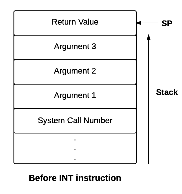
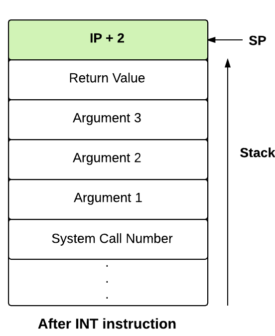
Now, you will write the system call handler for processing the write request.
INT 7
The write operation is handled by Interrupt 7. The word to be printed is passed from the user program through its user stack as the second argument to the interrupt routine. The interrupt routine retrieves this word from the stack and writes the word to the terminal using the OUT instruction.
Detailed instructions for doing so are given below
- Set the MODE FLAG field in the process
table to the system call number which is 5 for write system call. To get the process
table of current process, use the PID obtained from the system status table. MODE FLAG field in the process table is used to
indicate whether the current process is executing in a system call, exception handler or user
mode.
[PROCESS_TABLE + [SYSTEM_STATUS_TABLE + 1] * 16 + 9] = 5;
- Store the value of user SP in a register as we need it for further computations.
alias userSP R0;
userSP = SP;
- Switch the stack from user stack to kernel stack.
- Save the value of SP in the user SP field of Process Table entry of the process.
- Set the value of SP to beginning of the kernel stack.
- First we have to access argument 1 which is file descriptor to check whether it is valid or
not. In user mode, logical addresses are translated to physical address by the machine using
its
address translation scheme.
Since interrupts are executed in the kernel mode, the actual physical address is used to
access memory
locations. Hence to access the file descriptor (argument 1) we must calculate the physical
address of the memory location where it is stored. According to system call conventions,
userSP - 4 is the location of the argument 1. So we will manually address translate userSP -
4 (See contents of the stack after INT instruction in above image for reference).
alias physicalPageNum R1;
alias offset R2;
alias fileDescPhysicalAddr R3;
physicalPageNum = [PTBR + 2 * ((userSP - 4)/ 512)];
offset = (userSP - 4) % 512;
fileDescPhysicalAddr = (physicalPageNum * 512) + offset;
alias fileDescriptor R4;
fileDescriptor=[fileDescPhysicalAddr];
- Check whether the file descriptor obtained in above step is valid or not. In this stage it
should be -2 because file descriptor for console is -2. (see details here.) Write an IF condition to check whether file descriptor is -2 or
not.
if (fileDescriptor != -2)
then
	 //code when argument 1 is not valid
else
	 //code when argument 1 is valid
endif;
- If the file descriptor is not equal to -2, store -1 as a return value. According to system
call convention, return value is stored at memory location userSP -1 in the user stack.
Calculate physical address of the return value corresponding to userSP - 1 using address
translation mechanism.
if (fileDescriptor != -2)
then
	 alias physicalAddrRetVal R5;
	 physicalAddrRetVal = ([PTBR + 2 * ((userSP - 1) / 512)] * 512) + ((userSP - 1) % 512);
	 [physicalAddrRetVal] = -1;
else
	 //code when argument 1 is valid
endif;
- Calculate physical address of the argument 2 and extract the value from it , which is the
word to be printed to the console.
alias word R5;
word = [[PTBR + 2 * ((userSP - 3) / 512)] * 512 + ((userSP - 3) % 512)];
-
Write the word to the terminal using the print instruction.
print word;
-
Set the return value as 0 indicating success.
According to system call convention, return value is stored at memory location userSP -1 in
the user stack.
alias physicalAddrRetVal R6;
physicalAddrRetVal = ([PTBR + 2 * (userSP - 1)/ 512] * 512) + ((userSP - 1) % 512);
[physicalAddrRetVal] = 0;
- Outside the else block, set back the value of SP to point to top of user stack.
SP = userSP;
- Reset the MODE FLAG field in the process table to 0. Value 0 indicates that process is
running in user mode.
[PROCESS_TABLE + [SYSTEM_STATUS_TABLE + 1] * 16 + 9] = 0;
- Pass control back to the user program using the ireturn statement.
The following three steps has to be included in the else block.
Add code in the OS startup code to load INT7 from disk to memory.
loadi(16,29);
loadi(17,30);
Making Things Work
Note :[Implementation Tip] From this stage
onwards, you have to load multiple files using XFS-interface. To make things easier, create a
batch file containing XFS-interface commands to load the required files and run this batch file
using run command. See the usage of run command in XFS-interface documentation.
- Save this file in your UNIX machine as $HOME/myexpos/spl/spl_progs/sample_int7.spl
- Compile this program using the SPL compiler.
- Load the compiled XSM code as INT 7 into the XSM disk using XFS Interface.
- Run the Machine with timer disabled.
Note:Starting from the next stage, you will be writing
user programs using a high level language called
ExpL. ExpL allows you to write programs that invoke system calls using the exposcall() function .
The ExpL compiler will automatically generate code to translate your high level function call
to a call to the eXpOS
library and the library contains code to translate the call to an INT invocation as done
by you
in this stage. The next stage will introduce you to ExpL.
-
Q1. Why should we calculate the
physical address of userSP-3 and userSP-1
seperately instead of calculating one and adding/subtracting the difference from the
calculated value?
Suppose the physical address corresponding to logical address in userSP be - say 5000. it may not be the case that 4997 is the physical address corresponding to the logical address userSP-3. Similarly the physical address corresponding to userSP-1 need not be 4999. The problem is that the stack of a process spreads over two pages and these two physical pages need not be contiguous. Hence, logical addresses which are close together may be far separated in physical memory.
Assignment 1 : Write a program to print the first 20 numbers and run the system with timer enabled.
CloseExpL is a high level language in which you can write high level application programs. A compiler for ExpL supplied to you along with the eXpOS package will generate target code compatible with the eXpOS specification. ExpL permits application programs to call the function exposcall() that implements the high level library interface to the OS. Application programs must use this library interface to invoke eXpOS system calls. Certain built-in functions of the ExpL language (Alloc, Free and Initialize - these functions handle ExpL dynamic memory management) are also implemented as ExpL library routines. Note that the only way to invoke an eXpOS system call from a high level ExpL program is to use the exposcall() function.
The ExpL library file library.lib supplied to you along with the eXpOS package contains assembly language implementation of the library and occupies two pages of memory. The OS design stipulates that this library code must be pre-loaded to the XSM disk blocks 13 and 14 before OS bootstrap using XFS interface (see disk layout). Your OS start up code is supposed to load this code into memory pages 63 and 64 from disk blocks 13 and 14.
An ExpL program written by a programmer will contain library calls using the exposcall() function. The ExpL compiler will translate these calls to assembly instructions calling the library as specified here (see low level runtime library interface). The compiler expects that the library will be loaded to the logical address 0 of the address space of the program. The target code generated by the compiler will not contain the code for the library. Instead, the OS is expected to link this code (at physical pages 63 and 64) into logical pages 0 and 1 when the program is loaded for execution.
Hence, when the OS loads a program for execution, the library code must be linked to the logical pages 0 and 1 by setting the page table entries for the first two logical pages to 63 and 64. An ExpL program will contain calls to the library and hence the library linkage must be done correctly for ExpL program to run properly.
In the previous stages, you wrote and executed application programs in assembly language. Now, you will write application programs in ExpL and compile it to generate the assembly program. This compiled code is loaded into the XSM disk as done in previous stages.
- Below is the ExpL program to print numbers upto 50. Save this program as numbers.expl in
$HOME/myexpos/eXpl/samples.
This will be the init program in this stage.
Refer here for more examples of ExpL programs.
int main() { decl int temp,num; enddecl begin num=1; while ( num <= 50 ) do temp = exposcall ( "Write" , -2, num ); num = num + 1; endwhile; return 0; end } - Compile this program using the command
cd $HOME/myexpos/eXpl
./expl samples/numbers.expl
- Load the compiled code as the init program into the XSM disk using XFS Interface.
- Run the XSM machine.
The ExpL compiler will write the target executable code into the file assemblycode.xsm. (You
will have to
save the file to a different name before compiling the next ExpL program).
Note: The present version of ExpL compiles <filename>.expl into
<filename>.xsm. A copy of this target file is also wriiten into the file assemblycode.xsm
for backward compatibility.
-
Q1. If your ExpL program contains
read() function
call, will it work now?
Obviously not. The ExpL compiler will generate a call to the library requesting a console read; the library code in turn will generate an INT 6 for console input. Since you haven't written any code for INT 6, the OS will crash in INT 6. It will be an insightful exercise to trace the sequence of calls in debug mode.
Assignment 1 : Write an ExpL program to print all odd numbers from 1-100 and run the machine with this program loaded as the init.
Assignment 2 : Write an ExpL program to include a user defined type Student as follows
Student
{
    str name;
    int marks;
}
Assignment 3 : [Writing your own library] Instead of using the library implementation library.lib, write your own library (in assembly language) to support only the write system call to console. Your library code must extract arguments from the stack, check whether the request is for a console write, if so call INT 7 after supplying proper arguments in the stack as done in the previous stage. Upon return from the system call, your library routine must set the return value through the stack (setting return value in the proper location of the stack -see details here) and return control back to the application.
CloseThis stage introduces you to multi-programming. You will load two processes into memory during OS bootstrap and put them on concurrent execution. For this, you need to modify the timer interrupt handler to switch between the two processes.
We will use the the same init process as in stage 11. A second process called an idle process will also be set up in memory for execution during OS startup. The idle process simply contains an infinite loop.
You will modify the timer to implement a very primitive scheduler which shares the machine between the two processes. More detailed implementation of the OS scheduler will be taken up in later stages.
Idle ProgramIdle is a user program which is loaded for execution during OS bootstrap. Before OS bootstrap, it must be stored in the disk blocks 11 and 12. The OS bootstrap loader must load this program to memory pages 69 and 70 (See eXpOS Disk and Memory layout for details). The Page Table and Process Table for the idle process must be set up by the bootstrap loader. The PID of the idle process is fixed to be 0.
Idle program runs an infinite loop. The algorithm for the idle is as follows.while(1) do endwhile
An ExpL program for idle process is given below.
int main()
{
	decl
		int a;
	enddecl
	begin
		while(1==1) do
			a=1;
		endwhile;
		return 0;
	end
}
load --idle <...path to idle...>
Modifications to OS Startup Code
The eXpOS assigns each process a unique process ID (PID). The eXpOS design stipulates that the PID of idle process is 0. INIT program is assigned PID 1. Our implementation plan in this road map is to store the process table entry for the process with ID=0 in the 16 words starting at memory address PROCESS_TABLE, the process table entry for process with PID=1 in 16 words starting at memory address PROCESS_TABLE+16 and so on. Similarly, the page table for the process with PID=0 will be stored in 20 words starting at address PAGE_TABLE_BASE, page table for PID=1 will start at PAGE_TABLE_BASE+20 and so on. The memory layout design permits space for process/page table entries for a maximum of 16 processes. Thus, the OS can run at most 16 processes concurrently.
At present, we will run just two processes - the idle process with PID=0 and the init process with PID=1. Since there are two processes, we need to set up several data structures so that the operating system is able to keep track of the state of each process while in execution. The steps are described below.
- Load the idle code from disk to memory.
loadi(69,11);
loadi(70,12);
- Set the page table entries for idle process. As idle process does not use library functions
or
dynamic memory allocation, it doesn't need library and heap pages. Therefore, you need to set
up
entries for only the code and stack pages. As memory requirements of idle are very low,
we need to allocate only one physical page for stack.
We will allocate page 81 for stack as pages
76-80 will be used by the init process.
PTBR=PAGE_TABLE_BASE;  //as PID of idle process is 0

//Library
[PTBR+0] = -1;
[PTBR+1] = "0000";
[PTBR+2] = -1;
[PTBR+3] = "0000";

//Heap
[PTBR+4] = -1;
[PTBR+5] = "0000";
[PTBR+6] = -1;
[PTBR+7] = "0000";

//Code
[PTBR+8] = 69;
[PTBR+9] = "0100";
[PTBR+10] = 70;
[PTBR+11] = "0100";
[PTBR+12] = -1;
[PTBR+13] = "0000";
[PTBR+14] = -1;
[PTBR+15] = "0000";

//Stack
[PTBR+16] = 81;
[PTBR+17] = "0110";
[PTBR+18] = -1;
[PTBR+19] = "0000";
- We will run the INIT process of stage 11 (to print all numbers below 50) concurrently. Set the Page Table entries for init as done in previous stages with PTBR as PAGE_TABLE_BASE+20.
- As noted earlier, Process Table entries for idle starts from address PROCESS_TABLE and init from PROCESS_TABLE + 16. Set the PID field in the Process Table entry to 0 for idle and 1 for init.
- The process being currently scheduled is said to be in RUNNING state. The bootstrap loader will schedule the init process first. Thus, in the OS startup code, set the STATE field in process table entry of the idle process to CREATED and INIT process to RUNNING. The CREATED state indicates that the process had never been scheduled for execution previously. The need for a separate CREATED state will be explained later. Subsequent "re-scheduling" will be done by the timer interrupt handler. According to process table, STATE field occupies 2 words. In case of RUNNING and CREATED states, second word is not required. See process states.
- We will allocate the next free page, 82 as the User Area Page for the idle process. Set the User Area Page number field in the Process Table entry of idle to 82.
- Set the UPTR field in the Process Table entry for idle to 8*512 which is the logical address of user SP. (The reasoning behind this step was explained in detail in Stage 7).
- Set the KPTR field of the process table for idle to 0.
- Set the PTBR field to PAGE_TABLE_BASE and PTLR field to 10 in the Process Table entry of idle process.
- Set the entry point IP value from the header of idle process to top of the user stack of
the idle process as done in the previous stage.
[81 * 512] = [69*512 + 1];
- Set User Area Page number, UPTR, KPTR, PTBR and PTLR fields in the Process Table entry for init.
- Initialise the machine's PTBR and PTLR registers for scheduling the INIT process. (You have alreay gone through the steps in Stage 7).
- Set the Entry point address for INIT process in the beginning of Stack page of INIT. Also set the SP register accordingly.
- Set the current PID field in system status table to 1, as PID for INIT is 1.
- Transfer control to INIT using ireturn instruction.
The User Area Page Number field of a process table entry stores the page number of the user area page allocated to the process. The KPTR field must store the offset of the kernel stack pointer within this page. The UPTR points to the top of the current value of user stack pointer.
Some explanation is of the order here. When a process is executing in user mode, the active stack will be the user stack (logical pages 8-9 of the process). When the process switches to kernel mode, the first action by the kernel code will be to save the SP value to UPTR and set the SP register to the physical address of the top of the kernel stack. When a process enters the kernel mode from user mode, the kernel stack will always be empty. Hence, SP must be set to value (User Area Page Number * 512 - 1) whenever kernel mode is entered from the user mode.
Similarly, before a process executes IRET instruction and switch from kernel mode to user mode, the SP register must be set to previously stored value in UPTR field of the process table. The kernel stack will be empty when a process returns to user mode as there is no kernel context to be remembered.
The values of PTBR, PTLR, User Area Page Number, UPTR, KPTR etc. stored in the process table entry for a process will be used to set up the values of the hardware registers just before the process is scheduled for execution. We will not be scheduling the idle process immediately. Hence, the hardware registers will not be set based on the above values now. Instead, we will schedule the INIT process from the OS startup code. Hence your OS startup code must contain code to set up registers to schedule the INIT process, as outlined below:
Note: You must be clear with XSM unprivileged mode execution to understand the description that
follows.
Modifications to timer interrupt handler
In the previous stage you made the timer interrupt display "TIMER" at fixed intervals. However, the actual function of timer interrupt routine is to preempt the current running process and to transfer execution to another ready processes.
In this stage, you will write a sample scheduler which will schedule just two processes. The scheduler will be implemented in the timer interrupt handler. After saving the context of the currently executing process in its kernel stack, the scheduler must switch to the kernel stack to that of the next process to be scheduled. The context of the next process has to be loaded to the registers and then control of execution can be transferred to the process. Detailed intructions for scheduling are given below.
- Switch from the user stack to kernel stack of the currently executing process and save the register context using the backup instruction as done in stage 9.
- Obtain the PID of currently executing process from System Status Table .
alias currentPID R0;
currentPID = [SYSTEM_STATUS_TABLE+1];
- The Process table entry of the current process can be computed as PROCESS_TABLE +
currentPID*16.
Save the KPTR, PTBR and PTLR values to the Process Table entry of the current process.
Set the state of the process as READY.
Note that instead of saving the actual value of KPTR, we are saving KPTR%512. This is because the OS design stipulates that KPTR must contain the offset of the kernel stack pointer within the User Area Page. This is done so as to allow the OS to relocate the User Area Page if necessary.
alias process_table_entry R1;
process_table_entry = PROCESS_TABLE + currentPID * 16;

[process_table_entry + 12] = SP % 512;
[process_table_entry + 14] = PTBR;
[process_table_entry + 15] = PTLR;

[process_table_entry + 4] = READY;
- As we have only two processes to schedule, the scheduling algorithm we are going to use
will just toggle
between the two processes.
alias newPID R2;
if(currentPID == 0) then
	newPID = 1;
else
	newPID = 0;
endif;
- Restore the SP, PTBR and PTLR values from the Process Table entry for the new process.
alias new_process_table R3;
new_process_table = PROCESS_TABLE + newPID * 16;

//Set back Kernel SP, PTBR , PTLR
SP =  [new_process_table + 11] * 512 + [new_process_table + 12] ;
PTBR = [new_process_table + 14];
PTLR = [new_process_table + 15];
- Set the PID field of the System Status Table as newPID.
[SYSTEM_STATUS_TABLE + 1] = newPID;
-
Our scheduler must distinguish between two cases when a process is scheduled for execution.
If a process is in CREATED state, the process had never been scheduled for execution earlier.
Such a process will have no "history" to remember, and thus no "user context" to be restored
before being scheduled. On the other hand, a process in READY state is one which had been in
RUNNING state in the past. Such a process will have an associated (saved user context) which
the scheduler
would have saved in the kernel stack when it was scheduled out earlier. This context
has to be restored before the process is scheduled again for correct resumption of execution.
Check if the newly found process is in CREATED state. If so, set SP to top of its user stack and return to user mode.
if([new_process_table + 4] == CREATED) then
	[new_process_table + 4] = RUNNING;
	SP = [new_process_table + 13];
	ireturn;
endif;
Note:In this stage, the only situation where the timer finds the next process in CREATED state is when the IDLE process is to be scheduled for the first time. Since INIT is scheduled directly from the OS startup code, the INIT process never goes through the CREATED state. - Set the state of the newly found process as RUNNING.
[new_process_table + 4] = RUNNING;
- Restore the register context of the new process from its kernel stack and change the stack to user stack as done in previous stages. Note that if this is the case, then the process would have been in RUNNING state before.
Making Things Work
- Compile and load the modified OS statup code and Timer Interrupt handler to XSM disk.
- Compile and load the idle program into the XSM disk.
- Run the machine with timer enabled.
-
Q1.What is the significance of the
idle process?
The main purpose of the idle process is to run as a background process in an infinite loop. The idle process does nothing except running an infinite loop. This is demanded by the OS so that the scheduler will always have atleast one "READY" process to schedule. It is to be scheduled only when no other process is available for scheduling. However, in this stage we have scheduled idle just like any other process.
Assignment 1: Load a program to print numbers from 1-100 as the INIT program, and modify IDLE to print numbers from 101-200. (You will have to link the library to address space of IDLE for the Write function call to work.)
Assignment 2: Set two breakpoints (see SPL breakpoint instruction) in the timer interrupt routine, the first one immediately upon entering the timer routine and the second one just before return from the timer routine. Dump the process table entry and page table entries of current process (see XSM debugger for various printing options).
Close
-
Intermediate Stages:
In these stages, you will come across more advanced hardware features like, disk interrupt handling and exception handling. You will be implementing some basic kernel subsystems that will be used throughout the project. You will modularize your kernel into functional subsystems for resource management, memory management, device management, etc. You will implement a primitive user interface (Shell) and the final version of the OS loader (Exec system call). The amount of implementation details given in the road map will gradually diminish and many details will be left to be worked out by you. You wil need 3-4 weeks to complete these stages.
Modules in eXpOS are used to perform certain logical tasks, which are performed frequently. eXpOS modules serve various purposes like scheduling new process, acquiring and releasing resources etc. These modules run in kernel mode and are invoked only from the kernel mode. A user program can never invoke a module directly. Modules can be invoked from interrupt routines, other modules or the OS startup code.
As modules execute in kernel mode, the kernel stack of the currently scheduled process is used as the caller-stack for module invocation. XSM supports eight modules - MOD_0 to MOD_7 - which can be invoked using the CALL MOD_n / CALL <MODULE_NAME> instruction (see SPL constants). While switching to module, the CALL instruction pushes the IP address of the instruction following the CALL instruction on the top of the kernel stack and starts execution of the corresponding module. A module returns to the caller using the RET instruction (return statement in SPL) which restores the IP value present on the top of the kernel stack, pushed earlier by the CALL instruction. Note that we use the return statement, instead of the ireturn statement, to return to the caller. The IRET instruction (ireturn statement) changes mode from kernel to user as it assumes that SP contains a logical address. The RET instruction (return statement) on the other hand just returns to the caller in kernel mode, using the IP value pointed by SP. Read about kernel stack management during kernel module calls here.
A module in eXpOS may implement several functions, each for a particular task ( eg- resource manager module -module 0). Some modules may perform a single task (eg- scheduler, boot module). For a module with several functions, each function is given a function number to distinguish them within the module. This function number should be passed as argument in the register R1 along with other arguments in R2, R3 etc. Register R0 is reserved for return value. See SPL module calling conventions for details. For details about the OS functions implemented in various eXpOS modules, see here.
According to the memory organization of eXpOS, the OS startup code is provided with only one memory page (page numer 1). However, the code for OS startup may exceed one page due to initialization of several OS data structures. So we design a module for the purpose of OS initialization. This module will be called the Boot module (module 7). The Boot module is invoked from the OS startup code. The OS startup code hand-creates the idle process, initializes the SP register to the kernel stack of the idle process, loads module 7 in memory and then invokes the boot module (using the stack of the IDLE process). Upon return from the boot module, the OS startup code initiates user mode execution of the idle process. Note that in the previous stage, we had scheduled the INIT process first, before executing the IDLE pocess. Starting from the present stage, the idle process will be scheduled first. All further scheduling of processes will be controlled by the timer interrupt routine and a scheduler module, which will be discussed in the next stage. The Boot module is responsible for initialization of all eXpOS data structures, user processes and also loading of all interrupt routines and modules. You will not modify the OS startup code written in this stage in subsequent stages. However, you will add more code to the boot module as you go through various stages of the roadmap.
The idle process is run first to ensure that this process is scheduled at least once, so that its context gets initialized. This useful because in later stages, certain kernel operations (like disk swap) are performed from the context of the IDLE process. For now, we skip over this matter.
Modifications to OS startup code- Load module 7 from disk blocks 67 and 68 to memory pages 54 and 55 respectively, also load idle process from the disk to the corresponding memory pages.
- Set SP to (user area page number) * 512 -1. The user area page number for the idle process is 82 (as decided in the previous stage). This sets up a stack for calling the boot module.
- Call module 7 (boot module) using call statement in SPL.
call BOOT_MODULE;
- Setup the page table entries for the idle process as was done in the previous stage. Also set up PTBR to the page table base of the idle process. (The SPL constant PAGE_TABLE_BASE will point to the start of the page table of the idle process - figure out why.) Initialize PTLR (all user process in eXpOS must have PTLR=10).
- Initialize PID, UPTR, KPTR, PTBR, PTLR and user area page number fields in the Process Table entry for the idle process as was done in the previous stage.
- As the idle process is scheduled first, initialize the STATE field in the process table entry of the idle process as RUNNING and current PID field in the System Status Table to 0 (PID of the idle process).
- Transfer the entry point value from the header of the idle process to the top of the user stack of the idle process, as was done in the previous stage.
- Set the SP to the logical address of the user stack (8*512).
- Switch to the user mode using the ireturn statement.
/*The following code is executed after return from the boot module*/
Boot module
- Load all the required interrupts routines, eXpOS library, exception handler and the INIT process from the disk to the memory as was done in the OS startup code of the previous stage.
- Set the page table entries for INIT process as was done in the previous stage.
- Initialize the process table entry for the INIT process (setting PID, UPTR, KPTR, PTLR, PTBR, user area page number etc.) as was done in the previous stage.
- Set the STATE field in the process table entry of INIT to CREATED. (INIT will not be scheduled immedietely, as the idle process is going to be scheduled first.)
- Transfer the entry point value from the header of the INIT process to the top of the user stack of the INIT process, as was done in the previous stage.
- Return from module to OS startup code using return statement in SPL.
Making things work
Compile and load module 7 and the modified OS startup code to the disk using XFS interface. Run the XSM machine with timer enabled.
Assignment 1: Write ExpL programs to print even and odd numbers below 100. Modify the boot module code and the timer interrupt handler to schedule the two processes along with the idle process concurrently using the Round Robin scheduling algorithm.
Assignment 2: In the program of the previous assignment, add a breakpoint immediately upon entering the timer interrupt handler and print out in debug mode the contents of the page table entry and the process table entry of the current process (that is, the process from which timer was entered). You need to use use p and pt options of xsm debugger. Add another breakpoint just before return from the timer interrupt handler to print out the same contents.
Multiprogramming refers to running more than one process simultaneously. In this stage, you will implement an initial version of the Round Robin scheduler used in eXpOS. You will hand create another user process (apart from idle and init) and schedule its execution using the timer interrupt.
- Write an ExpL program to print the odd numbers from 1-100. Load this odd program as init.
load --init < path to odd.xsm >
- Write an ExpL program to print the even numbers from 1-100. Load this even program as an
executable.
load --exec < path to even.xsm >
Dump the inode table using dump --inodeusertable command in xfs-interface. Check the disk address of code blocks of even.xsm.
Using the --exec option of XFS interface, you can load an executable program into the XFS disk. XFS interface will load the executable into the disk and create Inode table entry for the file. XFS interface will also create a root entry for the loaded file. From the Inode Table Entry, you will be able to find out the disk blocks where the contents of the file are loaded by XFS interface. Recall that these were discussed in detail in Stage 2 :Understanding the File System )
Modifications to the boot module code
- Load the code pages of the even program from disk to memory.
- Set the Process Table entry and Page
Table entries for setting up a process for the
even program. You should set up the PTBR, PTLR, UPTR, KPTR, User Area Page Number etc. and
also initialize the process state as CREATED in the process table entry for the even process.
Set the PID field in the process table entry to 2.
Make sure that you do not allot memory pages that are already allotted to some other process or reserved for the operating system. - Set the starting IP of the new process on top of its user stack.
- We will implement the scheduler as a seperate module that can be invoked from the timer ISR
(Interrupt Service Routine).
The eXpOS design stipulates that
the scheduler is implemented as MODULE_5, and loaded in disk blocks 63 and 64 of the
XFS disk. The boot module must load this module from disk to memory pages 50 and 51. (We will take up
the implementation of the module soon below).
loadi(50,63);
loadi(51,64);
- First 3 process table entries are occupied. Initialize STATE field of all other process table entries to TERMINATED. This will be useful while finding the next process to schedule using round robin scheduling algorithm. Note that when the STATE field in the process table entry is marked as TERMINATED, this indicates that the process table entry is free for allocation to new processes.
Modifications to Timer Interrupt Routine
As we are going to write the scheduler code as a separate module (MOD_5), we will modify the timer interrupt routine so that it calls that module.
When the timer ISR calls the scheduler, the active kernel stack will be that of the currently RUNNING process. The scheduler assumes that the timer handler would have saved the user context of the current process (values of R0-R19 and BP registers) into the kernel stack before the call. It also assumes that the state of the process has been changed to READY. However, the machine's SP register will still point to the top of the kernel stack of the currently running process at the time of the call.
The scheduler first saves the values of the registers SP, PTBR and PTLR to the process table entry of the current process. Next, it must decide which process to run next. This is done using the Round Robin Scheduling algorithm. Having decided on the new process, the scheduler loads new values into SP, PTBR and PTLR registers from the process table entry of the new process. It also updates the system status table to store PID of new process. If the state of the new process is READY, then the scheduler changes the state to RUNNING. Now, the scheduler returns using the return instruction.
The control flow at this point is tricky and must be carefully understood. The key point to note here is that although the scheduler module was called by one process (from the timer ISR), since the stack was changed inside the scheduler, the return is to a program instruction in some other process! (determined by the value on top of the kernel stack of the newly scheduled process). The return is to that instruction which immediately follows the call scheduler instruction in the newly selected process. (why? - ensure that you understand this point clearly.) An exception to this rule happens only when the newly selected process to be scheduled is in the CREATED state. Here, the process was never run and hence there is no return address in the kernel stack. Hence, the scheduler directly kick-starts execution of the process by initiating user mode execution of the process (using the ireturn instruction). The design of eXpOS guarantees that a process can invoke the scheduler module only from the kernel mode. Consequently, the return address will be always stored on top of the kernel stack of the process.
The round robin scheduling algorithm generally schedules the "next process" in the process table that is in CREATED/READY state. (There are exceptions to this rule, which we will encounter in later stages.) Moreover, in the present stage, a process will invoke the scheduler only from the timer interrupt. We will see other situations in later stages.
As noted above, the timer resumes execution from the return address stored on the top of the kernel stack of the new process. The timer will restore the user context of the new process from the stack and return to the user mode, resulting in the new process being executed.
If the scheduler finds that the new process is in state CREATED and not READY, then as noted above, the timer ISR would not have set any return address in its kernel stack previously. In this case, the scheduler will set the state of the process to RUNNING and initialize machine registers PTLR and PTBR. Now, the scheduler proceeds to run the process in user mode. Hence, SP is set to the top of the user stack. The scheduler then starts the execution of the new process by transferring control to user mode using the IRET instruction.
The scheduler expects that when a process is in the CREATED state, the following values have been already set in the process table. (In the present stage, the OS startup code/Boot module is responsible for setting up these values.)
1. The state of the process has been set to CREATED.
2. The UPTR field of the process table entry has been set to the top of the user stack (and the stack-top contains the address of the instruction to be fetched next when the process is run in the user mode).
3. PTBR, PTLR, User Area Page Number and KPTR fields in the process table entry has been set up.
It is absolutely necessary to be clear about Kernel Stack Management during Module calls and Kernel Stack Management during Context Switch before proceeding further.
Modify the timer interrupt routine as explained above using the algorithm given here. (Ignore the part relating to the swapping operation as it will be dealt in a later stage.)
Context Switch Module (Scheduler Module)The scheduler module (module 5) saves the values of SP, PTBR and PTLR registers of the current process in its process table entry. It finds a new process to schedule which is in READY or CREATED state and has a valid PID (PID not equal to -1). Initialize the registers SP, PTBR, PTLR according to the values present in the process table entry of the new process selected for scheduling. Also update the System status table.
Write an SPL program for the scheduler module (module 5) as given below:
- Obtain the PID of the current process from the System Status Table .
- Push the BP of the current process on top of the kernel stack. (See the box below)
- Obtain the Process Table entry corresponding to the current PID.
- Save SP % 512 in the kernel stack pointer field, also PTBR and PTLR into the corresponding fields in the Process Table entry.
- Iterate through the Process Table entries, starting from the succeeding entry of the current process to find a process in READY or CREATED state.
- If no such process can be found, select the idle process as the new process to be scheduled. Save PID of new process to be scheduled as newPID.
- Obtain User Area Page number and kernel stack pointer value from Process Table entry of the new process and set SP as (User Area Page number) * 512 + (Kernel Stack pointer value).
- Restore PTBR and PTLR from the corresponding fields in the Process Table entry of the new process.
- Set the PID of the new process in the current PID field of the System Status Table.
- If the new process is in CREATED state, then do the following steps.
- Set SP to the value in the UPTR field of the process table entry.
- Set state of the newly scheduled process as RUNNING.
- Store 0 in the MODE FLAG field in the process table of the process.
- Switch to the user mode using the ireturn statement.
- Set the state of the new process as RUNNING.
- Restore the BP of the new process from the top of it's kernel stack.
- Return using return statement.
Note: In later stages you will modify the scheduler module to the final form given
here.
In the present stage, the scheduler module is called only from the time interrupt handler.
The timer interrupt handler already contains the instruction to backup the register context
of the current process. Hence, the scheduler does not have to worry about having to save the
user register context (including the value of the BP register) of the current process. What
then is the need for the scheduler to push the BP register?
The reason is that, in later stages, the scheduler may be called from kernel
modules other than the timer interrupt routine. Such calls typically happen when
an application invokes a system call and the system call
routine invokes a kernel module which in turn invokes the scheduler. Whenever this is the
case, the OS kernel expects that the application saves all the user mode registers except
the BP register before making the system call.
For instance, if the application is written in ExpL and compiled using the ExpL compiler
given to you, the compiler saves all the user registers except BP before making the
system call. The ExpL compiler expects that the OS will save the value of the BP register
before scheduling another application process. This explains why the scheduler needs to save
the BP register before a context switch.
Modifications to INT 10 handler
The ExpL compiler sets every user program to execute the INT 10 instruction (exit system call) at the end of execution to terminate the process gracefully. In previous stages, we wrote an INT 10 routine containing just a halt instruction. Hence, if any process invoked INT 10 upon exit, the machine would halt and no other process would execute further. However, to allow multiple processes to run till completion, INT 10 must terminate only the process which invoked it, and schedule other surviving processes. (INT 10 shall set the state of the dying process to TERMINATED). If all processes except idle are in TERMINATED state, then INT 10 routine can halt the system.
Write INT 10 program in SPL following below steps :
- Change the state of the invoking process to TERMINATED.
- Find out whether all processes except idle are terminated. In that case, halt the system. Otherwise invoke the scheduler There will be no return to this process as the scheduler will never schedule this process again.
Making things work
- Compile and load the Boot module code, timer interrupt routine, scheduler module (module 5) and interrupt 10 routine into disk using XFS interface.
- Run XSM machine with timer enabled.
-
Q1. When does the OS kernel invoke
the scheduler from some routine other than the timer interrupt handler?
In later stages, if a process gets blocked inside a kernel module (waiting for some resource), then the process will set its state to "WAITING" and will invoke the scheduler. Later when the process is back in READY state (as the resource becomes free) and the scheduler selects the process for running, execution returns to the instruction following the call to the scheduler in the kernel module.
Assignment 1: Write ExpL programs to print odd numbers, even numbers and prime numbers between 1 and 100. Modify the boot module code accordingly and run the machine with these 3 processes along with idle process.
Close
Processes in eXpOS require various resources like terminal, disk, inode etc. To manage these resources among different processes eXpOS implements a resource manager module (Module 0). Before the use of a resource, a process has to first acquire the required resource by invoking the resource manager. A process can acquire a resource if the resource is not already acquired by some other process. If the resource requested by a process is not available, then that process has to be blocked until the resource becomes free. In the meanwhile, other processes may be scheduled.
A blocked process must wake up when the requested resource is released by the process which had acquired the resource. For this, when a process releases a resource, the state of other processes waiting for the resource must be set to READY.
The resource manager module handles acquisition and release of system resources. A process must invoke the resource manager to acquire or release any system resource. The resource manager implements two functions for each resource - one to acquire the resource and the other to release the resource by a process. Details about different functions implemented in resource manager module are given here.
In this stage, you will learn how the terminal is shared by the processes for writing. The OS maintains a data structure called the Terminal Status Table. The Terminal Status table contains details of the process that has acquired the terminal. (Since there is only one terminal in the system, only one process is allowed to acquire the terminal at a time.) A flag named STATUS in the terminal status table indicates whether the terminal is available or not. When a process acquires the terminal, the PID of the process is updated in the terminal status table.
There are two functions related to terminal management in module 0. These are the Acquire Terminal and the Release Terminal functions. Each function has a function number to identify the function within the module. In the Resource Manager module, Acquire Terminal and Release Terminal have function numbers 8 and 9 respectively. When a module function is invoked, the function number (identifying the particular function within the module) is stored in register R1 and passed as argument to the module. The other arguments are passed through registers R2, R3 etc. See SPL module calling convention. For both Acquire Terminal and Release Terminal, PID of the currently running process needs to be passed as an argument through the register R2.
Acquire Terminal and Release Terminal are not directly invoked from the write system call. Write system call invokes a function called Terminal Write present in device manager module (Module 4). Terminal Write function acts as an abstract layer between the write system call and terminal handling functions in resource manager module. The function number for Terminal Write is 3 which is stored in register R1. The other arguments are PID of the current process and the word to be printed which are passed through registers R2 and R3 respectively. Terminal Write first acquires the terminal by calling Acquire Terminal. It prints the word (present in R3) passed as an argument. It then frees the terminal by invoking Release Terminal.
Since the invoked module will be modifying the contents of the machine registers during its execution, The invoker must save the registers in use into the (kernel) stack of the process before invoking the module. The module sets its return value in register R0 before returning to the caller. The invoker must extract the return value, pop back the saved registers and resume execution. SPL provides the facility to push and pop multiple registers in one statement using multipush and mutlipop respectively. Refer to the usage of multipush and multipop statements in SPL before proceeding further.
There is one important conceptual point to be explained here relating to resource acquisition. The Acquire Terminal function described above waits in a loop, in which it repeatedly invokes the scheduler if the terminal is not free. This kind of a waiting loop is called a busy loop or busy wait. Why can't the process wait just once for a resource and simply proceed to acquire the resource when it is scheduled? In other words, what is the need for a wait in a loop? Pause to think before you read the explanation below. You will encounter such busy loops several times in this project, inside various module functions described in later stages.
When a process invokes the scheduler waiting for a resource, the scheduler runs the process again only after the resource becomes free. However, the process may find that the resource is locked again when it tries to acquire the resource when it resumes execution. This happens because when a resource is released, all processes waiting for the resource are woken up by the OS. Only the one that get scheduled first will be able to lock the resource successfully. Other processes will have to wait for the resource repeatedly before finally acquiring the resource.
A better solution to the problem that avoids a busy loop is to have the resource manager maintain a request queue associated with each resource. When a process requests a resource, it registers itself into a resource queue and goes into wait state. When the resource is released, the release resource function can wake up only the process which is at head of the queue. This avoids unnecessary scheduling of all the waiting processes. Real systems implement resource queues for system resources that also maintains the priorities of various requesting processes. In eXpOS, we avoid using resource queues to make the implementation easier.
Note: We haven't saved any registers into the stack
while invoking the boot module from the OS startup code or the scheduler module from the
timer interrupt routine as there was no register context to be saved. However, to invoke
scheduler module from other modules or interrupt routines, it is necessary to save the
register context into the stack for proper resumption of execution.
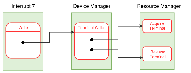
Modifying INT 7 routine
Interrupt routine 7 implemented in stage 10 is modified as given below to invoke Terminal Write function present in Device Manager module. Instead of print statement, write code to invoke Terminal Write function. Rest of the code remains intact.
- Push all registers used till now in this interrupt routine using multipush statement in
SPL.
multipush(R0, R1, R2, R3,...); // number of registers will depend on your code
- Store the function number of Terminal Write in register R1, PID of the current process in register R2 and word to be printed to the terminal in register R3.
- Call module 4 using call statement.
- Ignore the value present in R0 as Terminal Write does not have any return value.
- Use multipop statement to restore the registers pushed. Specify the same order of
registers used in multipush as registers are popped in the reverse order in which
they are specified in the multipop statement.
multipop(R0, R1, R2, R3,...);
Implementation of Module 4 (Device Manager Module)
In this stage, we will implement only Terminal Write function in this module.
- Function number and current PID are stored in registers R1 and R2. Give meaningful
names to these arguments.
alias functionNum R1;
alias currentPID R2;
- Terminal write function has a function number 3. If the functionNum is 3, implement the following steps else return using return statement.
- Push all the registers used till now in this module using the multipush statement in SPL as done earlier.
- Store the function number 8 in register R1 and PID of the current process from the System Status table in register R2 (Can use currentPID, as it already contain current PID value).
- Call module 0.
- Ignore the value present in R0 as Acquire Terminal does not have any return value.
- Use the multipop statement to restore the registers as done earlier.
- Print the word in register R3, using the print statement.
- Push all the registers used till now using the multipush statement as done earlier.
- Store the function number 9 in register R1 and PID of the current process from the System Status table in register R2 (Can use currentPID, as it already contain current PID value).
- Call module 0.
- Return value will be stored in R0 by module 0. Save this return value in any other register if needed.
- Restore the registers using the multipop statement.
- Return using the return statement.
Calling Acquire Terminal :-
Calling Release Terminal :-
Implementation of Module 0 code for terminal handling
- Function number is present in R1 and PID passed as an argument is stored in R2. Give
meaningful names to these registers to use them further.
alias functionNum R1;
alias currentPID R2;
- In Module 0, for the Acquire Terminal function (functionNum = 8) implement the following steps.
- The current process should wait in a loop until the terminal is free. Repeat
the following steps if STATUS field in the Terminal Status table is 1(terminal is
allocated to other process).
- Change the state of the current process in its process table entry to WAIT_TERMINAL.
- Push the registers used till now using the multipush statement.
- Call the scheduler to schedule other process as this process is waiting for terminal.
- Pop the registers pushed before. (Note that this code will be executed only after the scheduler schedules the process again, which in turn occurs only after the terminal was released by the holding process by invoking the release terminal function.)
- Change the STATUS field to 1 and PID field to currentPID in the Terminal Status Table.
- Return using the return statement.
- for the Release Terminal function (functionNum = 9) implement the following steps.
- currentPID and PID stored in the Terminal Status table should be same. If these are not same, then process is trying to release the terminal without acquiring it. If this case occurs, store -1 as the return value in register R0 and return from the module.
- Change the STATUS field in the Terminal Status table to 0, indicating terminal is released.
- Update the STATE to READY for all processes (with valid PID) which have STATE as WAIT_TERMINAL.
- Save 0 in register R0 indicating success.
- Return to the caller.
Modifying Boot Module code
- Load Module 0 from disk pages 53 and 54 to memory pages 40 and 41.
- Load Module 4 from disk pages 61 and 62 to memory pages 48 and 49.
- Initialize the STATUS field in the Terminal Status table as 0. This will indicate that the terminal is free before scheduling the first process.
Making things work
- Compile and load boot module code, module 0, module 4, modified INT 7 routine using XFS-interface.
- Run the machine with two programs one printing even numbers and another printing odd numbers from 1 to 100 along with the idle process.
-
Q1. According to eXpOS resource
management system introduced here, will Deadlock occur? If yes, explain it with a
situation. If no, which of the four conditions of Deadlock are not satisfied?
Deadlock will not occur according to the resource management system implemented here. As hold and wait, circular wait conditions are not satisfied (there is only one resource - the terminal - now).
See link for a set of neccessary conditions for deadlock.
Assignment 1: Set a breakpoint (see SPL breakpoint instruction) just before return from the Acquire Terminal and the Release Terminal functions in the Resource Manager module to dump the Terminal Status Table (see XSM debugger for various printing options).
Close
In this stage, we will introduce you to XSM console interrupt handling. A process must use the XSM instruction IN to read data from the console into the input port P0. IN is a privileged instruction and can be executed only inside a system call/module. Hence, to read data from the console, a user process invokes the read system call . The read system call invokes the Terminal Read function present in Device Manager module (Module 4). The IN instruction will be executed within this Terminal Read function.
The most important fact about the IN instruction is that it will not wait for the data to arrive in P0. Instead, the XSM machine continues advancing the instruction pointer and executing the next instruction. Hence there must be some hardware mechanism provided by XSM to detect arrival of data in P0.
When does data arrive in P0? This happens when some string/number is entered from the key-board and ENTER is pressed. At this time, the XSM machine will raise the console interrupt. Thus the console interrupt is the hardware mechanism that helps the OS to infer that the execution of the IN instruction is complete.
As noted above, the IN instruction is typically executed from the Terminal Read function. Since it is not useful for the process that invoked the Terminal Read function to continue execution till data arrives in P0, a process executing the IN instruction will sets its state to WAIT_TERMINAL and invoke the scheduler. The process must resume execution only after the XSM machine sends an interrupt upon data arrival.
When the console interrupt occurs, the machine interrupts the current process (note that some other process would be running) and executes the console interrupt handler. (The interrupt mechanism is similar to the timer interrupt. The current value of IP+2 is pushed into the stack and control transfers to the interrupt handler - see XSM machine execution tutorial for details). It is the responsiblity of the console interrupt handler to transfer the data arrived in port P0 to the process which is waiting for the data. This is done by copying the value present in port P0 into the input buffer field of the process table entry of the process which has requested for the input. Console interrupt handler also wakes up the process in WAIT_TERMINAL by setting its state to READY. (Other processes in WAIT_TERMINAL state are also set to READY by the console interrupt handler.)
Each process maintains an input buffer which stores the last data read by the process from the console. On the occurance of a terminal interrupt, the interrupt handler uses the PID field of the terminal status table to identify the correct process that had acquired the terminal for a read operation. The handler transfer the data from the input port to the input buffer of the process.
User programs can invoke the read system call using the library interface. For a terminal read, the file descriptor (-1 for terminal input) is passed as the first argument. The second argument is a variable to store number/string from console. Refer to the read system call calling convention here. ExpL library converts exposcall to low level system call interface for read system call, to invoke interrupt 6.
The read system call (Interrupt 6) invokes the Terminal Read function present in the Device manager Module. Reading from the terminal and storing the number/string (read from console) in the address provided is done by the Terminal Read function. Function number for the Terminal Read function, current PID and address where the word has to be stored are sent as arguments through registers R1, R2 and R3 respectively. After coming back from Terminal Read function, it is expected that the word address (passed as argument to read system call) contains the number/string entered in the terminal.
The OS maintains a global data structure called the terminal status table that stores information about the current state of the terminal. A process can acquire the terminal by invoking the Acquire Terminal function of the resource manager module . When the Acquire Terminal function assigns the terminal to a process, it enters the PID of the process into the PID field of the terminal status table. The Terminal Read function must perform the following 1) Acquire the terminal 2) Issue an IN instruction (SPL read statement translates to XSM instruction IN) 3) Set its state as WAIT_TERMINAL 4) Invoke the scheduler and 5) After console interrupt wakes up this process, transfer data present in the input buffer field of the process table into the word address (passed as an argument).
Read about XSM interrupts before proceeding further.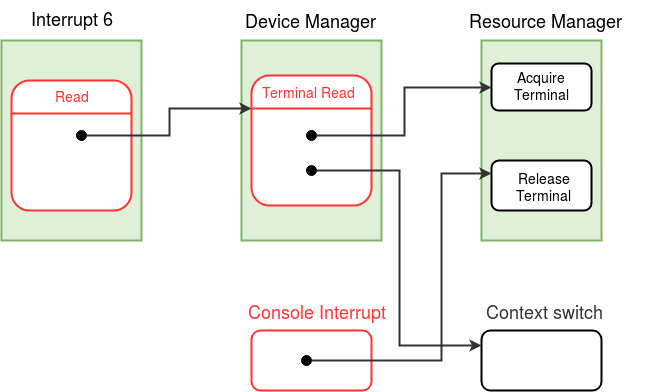
Implementation of read system call (interrupt 6 routine)
- Set the MODE FLAG in the process table of the current process to the system call number which is 7 for read system call.
- Save the value of register SP as userSP.
alias userSP R0;
userSP=SP;
- Store the value of register SP in the UPTR field of the process table entry of the current process.
- Initialize SP (kernel stack pointer) to (user area page number)*512 -1.
- Retrieve the file descriptor from the user stack, stored at userSP-4.
- If the file descriptor is not -1
- Store -1 as the return value in the user stack (at position userSP-1).
- If the file descriptor is -1, implement below steps.
- Retrieve the word address sent as an argument from the user stack (userSP-3).
- Push all the registers used till now in this interrupt.
- Save the function number of the Terminal Read function in the register R1. Save PID of the current process and the word address obtained above in registers R2 and R3 respectively.
- Call device manager module.
- Restore the registers.
- Store 0 as return value in the user stack indicating success.
There is no return value for terminal Read.
- Reset the MODE FLAG in the process table to 0.
- Change SP back to user stack and return to the user mode.
Modification to Device manager Module
In previous stage we implemented Terminal Write function in module 4, now we will add Terminal Read function.
- If function number in R1 corresponds to Terminal Read, then implement below steps.
- Push all the registers used till now using multipush.
- Initialize registers R1, R2 with function number of Acquire Terminal and PID of current process respectively.
- Call resource manager module.
- Restore the registers using the multipop statement.
- Use read statement, for requesting to read from the terminal.
read;
- Change the state of the current process to WAIT_TERMINAL.
- Push all the registers used till now.
- Invoke the scheduler.
- Restore the registers using the multipop statement.
- The logical address of the word where the data has to be stored is in R3. Convert this logical address to physical address.
- Store the value present in input buffer field of process table to the obtained physical address of the word.
- Return to the caller.
Calling Acquire Terminal function :-
Invoking the Context Switch Module :-
Following steps are executed after return from the scheduler
Implementation of Console Interrupt Handler
/* The console interrupt handler is entered while some other process is executing in the user mode. The handler must switch to the kernel stack of that process, do the interrupt handling, restore the user stack of the process that was running and return control back to the process */
- Store the SP value in the UPTR field in the process table entry of the currently running process.
- Initialize SP (kernel stack pointer) to (user area page number)*512 -1. //Switch to the kernel stack.
- Backup the user context of the currently running process in the kernel stack as done in timer interrupt routine.
- Get the PID of the process that has aqcuired the terminal from the terminal status table, Save this as reqPID.
- Using the reqPID obtained in the above step, get the corresponding process table entry.
- The input entered in the console is saved in port P0 by the XSM machine. Copy the value present in P0 into the input buffer field of the process table entry obtained in the above step.
- Push the registers used in this interrupt.
- Initialize register R1 with function number for release terminal, R2 with reqPID (The current process did not acquire the terminal. The process with reqPID as PID is holding the terminal.)
- Call resource manager module.
- Ignore the return value and restore the registers pushed before.
- Restore the user context from the kernel stack as done in the timer interrupt routine.
- Change SP to UPTR field from the process table entry of the currently running process and return to the user mode. //Switch back to user stack
/*next release the terminal */
Modification to Boot Module
- Load console interrupt handler and interrupt 6 from disk to memory.
- Remove the initialization of the third process, as we will run only idle and init processes in this stage.
Making things work
- Compile and load boot module code, console interrupt and interrupt 6 using XFS interface.
- Write an ExpL program which reads two numbers from console and finds the GCD using Euclidean's algorithm and print the GCD. Load this program as init program.
-
Q1. Is it possible that, the running
process interrupted by the console interrupt be the same process that had acquired the
terminal for reading?
No, The process which has acquired the terminal will be in WAIT_TERMINAL state after issuing a terminal read until the console interrupt occurs. Hence, this process will not be scheduled until console interrupt changes it's state to READY.
Assignment 1: Write an ExpL program to read N numbers in an array, sort using bubble sort and print the sorted array to the terminal. Load this program as init program and run the machine.
Assignment 2: Use the XSM debugger to print out the contents of the Terminal Status Table and the input buffer (by dumping process table entry of the process to which read was performed) before and after reading data from the input port to the input buffer of the process, inside the terminal interrupt handler.
Close
In this stage, you will be working on the implementation of the exec system call. Exec is the "program loader" of eXpOS. Exec takes as input a filename. It first checks whether the file is a valid eXpOS executable stored in the XSM disk, adhering to the XEXE format. If so, Exec destroys the invoking process, loads the executable file from the disk, and sets up the program for execution as a process. A successful exec operation results in the termination of the invoking process and hence never returns to it.
Name of the executable file is the only input to the exec system call. This file should be present in the disk before starting the machine. The inode index of this file can be obtained by going through the memory copy of the inode table.
Note :From here onwards whenever the inode table is
referred, it is implied that memory copy of the inode table is referred (unless mentioned
otherwise). Inode table is loaded from the disk to the memory in Boot Module.
Exec first deallocates all pages the invoking process is using. These include two heap pages, two user stack pages, code pages occupied by the process and the user area page. It also invalidates the entries of the page table of the invoking process. Note that the newly scheduled process will have the same PID as that of the invoking process. Hence the same process table entry and page table of the invoking process will be used by the newly loaded process. Exec calls the Exit Process function in the process manager module (module 1) to deallocate the pages and to terminate the current process.
As mentioned earlier, Exit Process function releases the user area page of the current process. Since Exec system call runs in kernel mode and needs a kernel stack for its own execution, after coming back from Exit process function, exec reclaims the same user area page for the new process. Further, exec acquires two heap, two stack and the required number of code pages (number of disk blocks in the inode entry of the file in the inode table) for the new process. New pages will be acquired by invoking the Get Free Page function present in the memory manager module (module 2). Page table is updated according to the new pages acquired. Code blocks for the new process are loaded from the disk to the memory pages obtained. For loading blocks into the memory pages, we use immediate load (loadi statement in SPL). Finally, exec initializes the IP value of new process on top of its user stack and initiates execution of the newly loaded process in the user mode.
eXpOS maintains a data structure called memory free list in page 57 of the memory. Each Page can be shared by zero or more processes. There are 128 entries in the memory free list corresponding to each page of memory. For each page, the corresponding entry in the list stores the number of processes sharing the page. The constant MEMORY_FREE_LIST gives the starting address of the memory free list.
Now we will understand the working of the module functions that exec uses during its execution. Before proceeding further have a careful look of the diagram to understand the overall working of the exec system call.
- Exit Process (function number = 3, process manager module)
- Free Page Table (function number = 4, process manager module)
- Free User Area Page (function number = 2, process manager module)
- Release Page (function number = 2, memory manager module)
- Get Free Page (function number = 1, memory manager module)
The first function invoked in the exec system call is the Exit Process function. Exit Process function takes PID of a process as an argument (In this stage, PID of the current process is passed). Exit process deallocates all the pages of the invoked process. It deallocates the pages present in the page table by invoking another function called Free Page Table present in the same module. Further, The Exit Process deallocates the user area page by invoking Free User Area Page in the same module. The state of the process (corresponding to the given PID) is set to TERMINATED. This is not the final Exit process function. There will be minor modifications to this function in the later stages.
The Free Page Table function takes PID of a process as an argument (In this stage, PID of the current process is passed). In the function Free Page Table , for every valid entry in the page table of the process, the corresponding page is freed by invoking the Release Page function present in the memory manager module. Since the library pages are shared by all the processes, do not invoke the Release Page function for the library pages. Free Page Table function invalidates all the page table entries of the process with given PID. The part of the Free Page Table function involving updates to the Disk Map Table will be taken care in subsequent stages.
The function Free User Area Page takes PID of a process (In this stage, PID of the current process is passed) as an argument. The user area page number of the process is obtained from the process table entry corresponding to the PID. This user area page is freed by invoking the Release Page function from the memory manager module. However, since we are using Free User Area Page to release the user area page of the current process one needs to be careful here. The user area page holds the kernel stack of the current process. Hence, releasing this page means that the page holding the return address for the call to Free User Area Page function itself has been released! Neverthless the return address and the saved context of the calling process will not be lost. This is because Release Page function is non blocking and hence the page will never be allocated to another process before control transfers back to the caller. (Free User Area Page function also releases the resourses like files and semaphores acquired by the process. We will look into it in later stages.)
The Release Page function takes the page number to be released as an argument. The Release Page function decrements the value in the memory free list corresponding to the page number given as an argument. Note that we don't tamper with the content of the page as the page may be shared by other processes. The system status table keeps track of number of free memory pages available to use in the MEM_FREE_COUNT field. When the memory free list entry of the page becomes zero, no process is currently using the page. In this case, increment the value of MEM_FREE_COUNT in the system status table indicating that the page has become free for fresh allocation. Finally, Release page function must check whether there are processes in WAIT_MEM state (these are processes blocked, waiting for memory to become available). If so, these processes have to be set to READY state as memory has become available now. At present, the OS does not set any process to WAIT_MEM state and this check is superfluous. However, in later stages, the OS will set processes to WAIT_MEM state when memory is temporarily unavailable, and hence when memory is released by some process, the waiting processes have to be set to READY state.
To acquire the pages for the new process, exec calls the module function Get Free Page. The function returns the page number of the page allocated. Fundamentally, Get Free page searches through the memory free list to find a free page for the allocation. If a free page is found, memory free list entry corresponding to that page is incremented and number of the page found is returned.
If no memory page is free (MEM_FREE_COUNT in the system status table is 0), then state of the process is changed to WAIT_MEM and the scheduler is invoked. This process is scheduled again, when the memory is available (state of this process is changed to READY by some other process). The field WAIT_MEM_COUNT in the system status table stores the number of processes waiting to acquire a memory page. The Get Free Page function increments the WAIT_MEM_COUNT before changing state to WAIT_MEM. The process waits in the WAIT_MEM state until any memory page is available for use. Upon waking up, the Get Free Page function allocates the free memory page and updates the WAIT_MEM_COUNT and MEM_FREE_COUNT in the system status table.
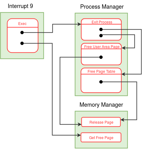
Implementation of Exec system call
Exec has system call number as 9 and it is implemented in interrupt routine 9. Follow steps below to implement interrupt routine 9.
- Save user stack value for later use, set up the kernel stack. (see kernel stack management during system calls.)
- Set the MODE FLAG in the process table to system call number of exec.
- Get the argument (name of the file) from user stack.
- Search the memory copy of the inode table for the file, If the file is not present or file is not in XEXE format return to user mode with return value -1 indicating failure (after setting up MODE FLAG and the user stack).
- If the file is present, save the inode index of the file into a register for future use.
- Call the Exit Process function in process manager module to deallocate the resources and pages of the current process.
- Get the user area page number from the process table of the current process. This page has been deallocated by the Exit Process function. Reclaim the same page by incrementing the memory free list entry of user area page and decrementing the MEM_FREE_COUNT field in the system status table. (same user area page is reclaimed - why?)
- Set the SP to the start of the user area page to intialize the kernel stack of the new process.
- New process uses the PID of the terminated process. Update the STATE field to RUNNING and store inode index obtained above in the inode index field in the process table.
- Allocate new pages and set the page table entries for the new process.
- Set the library page entries in the page table. (must be set to read only-why? Note that library page need not be allocated.)
- Invoke the Get Free Page function to allocate 2 stack and 2 heap pages. Also validate the corresponding entries in page table.
- Find out the number of blocks occupied by the file from inode table. Allocate same number of code pages by invoking the Get Free Page function and update the page table entries.
- Load the code blocks from the disk to the memory pages using loadi statement. (We will change this step in the next stage.)
- Store the entry point IP (present in the header of first code page) value on top of the user stack.
- Change SP to user stack, change the MODE FLAG back to user mode and return to user mode.
Note: The implementation of some of the module functions
given below are primitive versions of their final versions. The present versions are just
sufficient for the purposes of this stage. These functions may require modifications in later
stages. The required
modifications will be explained at appropriate points in the roadmap.
Implementation of Process Manager Module (Module 1)
- According to the function number value present in R1, implement different functions in module 1.
- If the function number corresponds to Free User Area Page, follow steps below
- Obtain the user area page number from the process table entry corresponding to the PID given as an argument.
- Free the user area page by invoking the Release Page function.
- Return to the caller.
- If the function number corresponds to Exit Process, follow steps below
- Extract PID of the invoking process from the corresponding register.
- Invoke the Free Page Table function with same PID to deallocate the page table entries.
- Invoke the Free user Area Page function with the same PID to free the user area page.
- Set the state of the process as TERMINATED and return to the caller.
- If the function number corresponds to Free Page Table, follow steps below
- Invalidate the page table entries for the library pages by setting page number as -1 and auxiliary data as "0000" for each entry.
- For each valid entry in the page table, release the page by invoking the Release Page function and invalidate the entry.
- Return to the Caller.
Note :The implementation of above three functions of
process manager module are not final versions. They will be updated as required in later
stages.
Implementation of Memory Manager Module (Module 2)
- According to the function number value present in R1, implement different functions in module 2.
- If the function number corresponds to Get Free Page, follow steps below
- Increment WAIT_MEM_COUNT field in the system status table. //Do not increment the WAIT_MEM_COUNT in busy loop (an important step )
- While memory is full (MEM_FREE_COUNT will be 0), do following.
- Set the state of the invoked process as WAIT_MEM.
- Schedule other process by invoking the context switch module. // blocking the process
- Decrement the WAIT_MEM_COUNT field and MEM_FREE_COUNT field in the system status table.
- Find a free page using memory free list and set the corresponding entry as 1. Make sure to store the obtained free page number in R0 as return value.
- Return to the caller.
/* Note the sequence - increment WAIT_MEM_COUNT, waiting for the memory, decrement WAIT_MEM_COUNT.*/
- If the function number corresponds to Release Page, follow steps below
- The Page number to be released is present in R2. Decrement the corresponding entry in the memory free list.
- If that entry in the memory free list becomes zero, then the page is free. So increment the MEM_FREE_COUNT in the system status table.
- Update the STATUS to READY for all processes (with valid PID) which have STATUS as WAIT_MEM.
- Return to the caller.
Note : The Get Free Page and Release Page functions
implemented above are final versions according to the algorithm given in memory manager module.
Modifications to the Boot Module.
- Load interrupt routine 9, module 1, module 2 and inode table from the disk to the memory. Refer to disk and memory organization here.
- Initialize the memory free list with value 1 for pages used and 0 for free pages.
- Initialize the fields WAIT_MEM_COUNT to 0 and MEM_FREE_COUNT to number of free pages in the system status table.
ExpOS memory layout for the XSM machine sets pages 76-127 as free pages and the remaining are reserved for OS modules, OS data structures, interrupts, system calls, code region of special processes (INIT, shell), the OS library etc. Hence, the initial setting of the memory free list should mark pages 76-127 as free (value 0) and the rest as allocated (value 1). The memory manager shall be doing allocation and deallocation only from the free pool (76-127). The boot module/OS startup code further allocates space for the user-area page and stack pages for INIT and IDLE processes from this free pool. The INIT process require two additional pages for the heap. The pages allocated to INIT process are- stack-76, 77, heap-78, 79, user area page-80 and for IDLE process- stack-81, user area page-82. Hence, the effective free pool (MEM_FREE_COUNT value) at the end of OS initialization process starts from memory page 83.
Making things work
- Compile and load interrupt routine 9, module 1 and module 2 using XFS-interface. Run the machine.
-
Q1. Why does exec reclaim the same
user area page for the new process? (As done in step 7 of exec system call
implementation.)
Since the page storing the kernel context has been de-allocated, before making any function call, a stack page has to be allocated to store parameters, return address etc. It is unsafe to invoke the Get Free Page function of the memory manager module before allocating a stack page (why?).
-
Q2. Why should the OS set the WRITE
PERMISSION BIT for library and code pages in each page table entry to 0, denying
permission for the process to write to these pages?
ExpOS does not expect processess to modify the code page during execution. Hence, during a fork() system call (to be seen in later stages), the code pages are shared between several processes. Similarly, the library pages are shared by all processes. If a process is allowed to write into a code/library page, the shared program/library will get modified and will alter the execution behaviour of other processes, which violates the basic virtual address space model offered by the OS.
Assignment 1: [Shell version-I] Write an ExpL program to read the name of program from the console and execute that program using exec system call. Load this program as INIT program and run the odd.expl (printing odd numbers between 1-100) program using the shell.
Assignment 2: Use the XSM debugger to print out the contents of the System Status Table and the Memory Free List after Get Free Page and Release Page functions, inside the Memory Manager module.
Close
In this stage, we will introduce disk interrupt handling in XSM. In the previous stage, we used the loadi statement to load a disk block into a memory page. When the loadi statement (immediate load) is used for loading, the machine will execute the next instruction only after the block transfer is complete by the disk controller. A process can use the load statement instead of loadi to load a disk block to a memory page. The load statement in SPL translates to LOAD instruction in XSM.
The LOAD instruction takes two arguments, a page number and a block number. The LOAD instruction initiates the transfer of data from the specified disk block to the memory page. The XSM machine doesn't wait for the block transfer to complete, it continues with the execution of the next instruction. Instead, the XSM machine provides a hardware mechanism to detect the completion of data transfer. XSM machine raises the disk interrupt when the disk operation is complete.
In real operating systems, the OS maintains a software module called the disk device driver module for handling disk access. This module is responsible for programming the disk controller hardware for handling disk operations. When the OS initiates a disk read/write operation from the context of a process, the device driver module is invoked with appropriate arguments. In our present context, the device manager module integrates a common "driver software" for all devices of XSM. The load and store instructions actually are high level "macro operations" given to you that abstract away the low level details of the device specific code to program the disk controller hardware. The loadi instruction abstracts disk I/O using the method of polling whereas the load instruction abstracts interrupt based disk I/O.
To initiate the disk transfer using the load statement, first the process has to acquire the disk. This ensures that no other process uses the disk while the process which has acquired the disk is loading the disk block to the memory page. eXpOS maintains a data structure called Disk Status Table to keep track of these disk-memory transfers. The disk status table stores the status of the disk indicating whether the disk is busy or free. The disk status table has a LOAD/STORE bit indicating whether the disk operation is a load or store. The table also stores the page number and the block number involved in the transfer. To keep track of the process that has currently acquired the disk, the PID of the process is also stored in the disk status table. The SPL constant DISK_STATUS_TABLE gives the starting address of the Disk Status Table in the XSM memory.
After the current process has acquired the disk for loading, it initializes the Disk Status Table according to the operation to be perfromed (read/write). The process then issues the load statement to initiate the loading of the disk block to the memory page. As mentioned earlier, the XSM machine does not wait for the transfer to complete. It continues with the execution of the next instruction. However, virtually in any situation in eXpOS, the process has to wait till the data transfer is complete before proceeding (why?). Hence, the process suspends its execution by changing its state to WAIT_DISK and invokes the scheduler, allowing other concurrent processes to run. (At present, the only concurrent process for the OS to schedule is the IDLE process. However, in subsequent stages we will see that the OS will have more meaningful processes to run.)
When the load/store transfer is complete, XSM machine raises the hardware interrupt called the disk interrupt. This interrupt mechanism is similar to the console interrupt. Note that when disk interrupt occurs, XSM machine stops the execution of the currently running process. The currently running process is not the one that has acquired the disk (why?). The disk interrupt handler releases the disk by changing the STATUS field in the Disk Status table to 0. It then wakes up all the processes waiting for the disk (by changing the STATE from WAIT_DISK to READY) which also includes the process which is waiting for the disk-transfer to complete. Then returns to the process which was interrupted by disk controller.
XSM machine disables interrupts when executing in the kernel mode. Hence, the disk controller can raise an interrupt only when the machine is executing in the user mode. Hence the OS has to schedule "some process" even if all processess are waiting for disk/terminal interrupt - for otherwise, the device concerned will never be able to interrupt the processor. The IDLE process is precisely designed to take care of this and other similar situations.
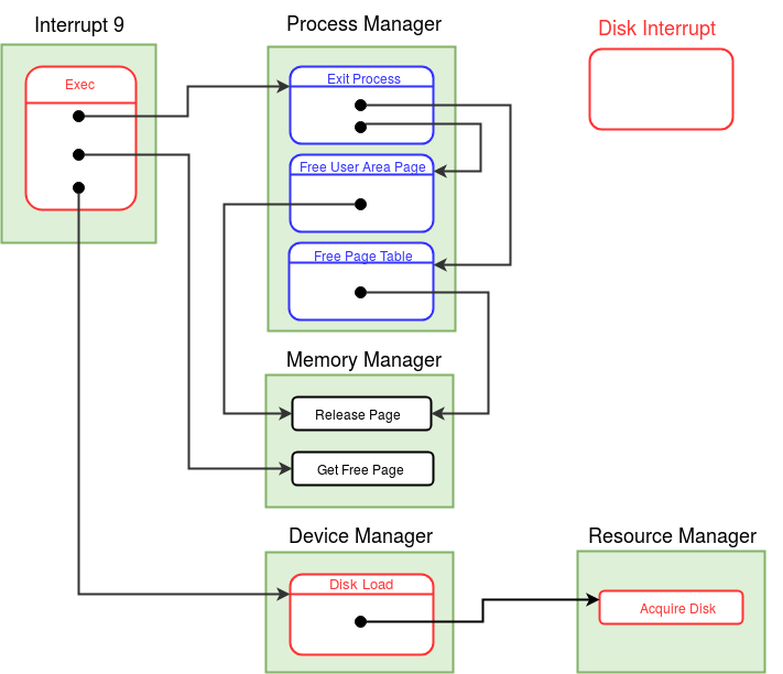
In this stage, you have to modify the exec system call by replacing the loadi statement by a call to the Disk Load function. The Disk Load function (in device manager module), the Acquire Disk function (in resource manager module) and the disk interrupt handler must also be implemented in this stage. Minor modifications are also required for the boot module.
- Disk Load (function number = 2, device manager module)
- Acquire Disk (function number = 3, resource manager module)
- Implementation of Disk Interrupt handler
- Modification to exec system call (interrupt 9 routine)
- Modifications to boot module
The Disk Load function takes the PID of a process, a page number and a block number as
input and performs the following tasks :
1) Acquires the disk by invoking the Acquire
Disk function in the resource manager
module (module 0)
2) Set the Disk Status table
entries as mentioned in the algorithm (specified in the above link).
3) Issue the load statement to initiate a disk
block to memory page DMA transfer.
4) Set the state of the process (with given PID) to
WAIT_DISK and invoke the scheduler.
The Acquire Disk function in the resource manager module takes the PID of a process as an
argument. The Acquire disk function performs the following tasks :
1) While the disk is busy (STATUS field in the Disk Status Table is 1), set the state of
the process to WAIT_DISK and invoke the scheduler.
/* When the disk is finally free,
the process is woken up by the disk interrupt handler.*/
2) Lock the disk by setting
the STATUS and the PID fields in the Disk Status Table to 1 and PID of the process
respectively.
Note : Both Disk Load and Acquire Disk module
functions implemented above are final versions according to the algorithm given in
respective modules.
When the disk-memory transfer is complete, XSM raises the disk interrupt. The disk
interrupt handler then performs the following tasks :
1) Switch to the kernel stack and back up the register context.
2) Set the STATUS field in the Disk Status table to 0 indicating that disk is no longer
busy.
3) Go through all the process table entries, and change the state of the process to
READY, which is in WAIT_DISK state.
4) Restore the register context and return to user mode using the ireturn statement.
Note: There is no Release Disk function to release
the disk instead the disk interrupt handler completes the task of the Release Disk
function.
Instead of the loadi statement used to load the disk block to the memory page, invoke the Disk Load function present in the device manager module.
We will initialize another data strucutre as well in this stage. This is the per-process resource table. (This step can be deferred to later stages, but since the work involved is simple, we will finish it here). The per-process resource table stores the information about the files and semaphores which a process is currently using. For each process, per-process resource table is stored in the user area page of the process. This table has 8 entries with 2 words each, in total it occupies 16 words. We will reserve the last 16 words of the User Area Page to store the per-process Resource Table of the process. In exec, after reacquiring the user area page for the new process, per-process resource table should be initialized in this user area page. Since the newly created process has not opened any files or semaphores, each entry in the per-process table is initialized to -1.
Following modifications are done in boot module :
1) Load the disk interrupt routine from the disk to the memory.
2) Initialize the STATUS field in the Disk Status Table to 0.
3) Initialize the per-process
resource table of init process.
Compile and load the modified and newly written files into the disk using XFS-interface. Run the Shell version-I with any program to check for errors.
-
Q1. Can we use the load statement
in the boot module code instead of the loadi statement? Why?
No. The modules needed for the execution of load, need to be present in the memory first. And even if they are present, at the time of execution of the boot module, no process or data structures are initialized (like Disk Status Table).
-
Q2. Why does the disk interrupt
handler has to backup the register context?
Disk interrupt handler is a hardware interrupt. When disk interrupt occurs, the XSM machine just pushes IP+2 value on stack and transfers control to disk interrupt. Occurance of a hardware interrupt is unexpected. When the disk interrupt is raised, the process will not have control over it so the process (curently running) cannot backup the registers. That's why interrupt handler must back up the context of the process (currently running) before modifying the machine registers. The interrupt handler also needs to restore the context before returning to user mode.
-
Q3. Why doesn't system calls
backup the register context?
The process currently running is in full control over calling the interrupt (software interrupt) corresponding to a system call. This allows a process to back up the registers used till that point (not all registers). Note that instead of process, the software interrupt can also back up the registers. But, the software interrupt will not know how many registers are used by the process so it has to back up all the registers. Backing up the registers by a process saves space and time.
-
Q4. Does the XSM terminal input
provide polling based input?
Yes, readi statement provided in SPL gives polling based terminal I/O. But readi statement only works in debug mode. Write operation is always asynchronous.
Assignment 1: Use the XSM debugger to print out the contents of the Disk Status Table after entry and before return from the disk interrupt handler.
Close
This stage introduces you to exception handling in eXpOS. There are four events that result in generation of an exception in XSM. These events are a) illegal memory access, b) illegal instruction, c) arithmetic exception and d) page fault. When one of this events occur, the XSM machine raises an exception and control is transferred to the exception handler. The exception handler code used in previous stages contains only halt instruction which halts the system in the case of an exception. Clearly it is inappropriate to halt the system (all the processes are terminated) for exception occured in one process. In this stage, we implement the exception handler which takes appropriate action for each exception. The exception handler occupies page 2 and 3 in the memory and blocks 15 and 16 in the disk. See disk and memory organization here. There are 4 special registers in XSM which are used to obtain the cause of the exception and the information related to the exception. These registers are EC, EIP, EPN and EMA. The cause of the exception is obtained from the value present in the EC register.
Exception handler mechanism gives a facility to resume the execution of the process after the corresponding exception has been taken care of. It is not always possible to resume the execution of the process, as some events which cause the exception cannot be corrected. In this case, the proper action is to halt the process gracefully. For the events 1) illegal memory access (EC=2) 2) illegal instruction (EC=1) and 3) arithmetic exception (EC=3), the exception handler just prints the cause of the exception. These cases occur because the last instruction executed (in the currently running user process) resulted in the corresponding error condition. As the OS is not reponsible for correcting these conditions (why?), the exception handler halts the process gracefully and then invokes the scheduler to run other processes.
The page fault exception (EC=0) occurs when the last instruction in the currently
running application tried to either -
a) Access/modify data from a legal address within its address space, but the page
was set to invalid in the page table or
b) fetch an instruction from a legal address
within its address space, whose page table entry is invalid.
In either case, the exception occured not because of any error from the side of the application, but because the OS had not loaded the page and set the page tables. In such case, the exception handler resumes the execution of the process after allocating the required page(s) for the process and attaching the page(s) to the process (by setting page table entries appropriately). If the faulted page is a code page, the OS needs to load the page from the disk to the newly allocated memory.
But why should the OS not allocate all the pages required for a process when the process is initialized by the Exec system call, as we were doing in the previous two stages? The reason is that this method of pre-allocation allows fewer concurrent processes to run than with the present strategy of "lazy allocation" to be described now. The strategy followed in this stage is to start executing a process with just one page of code and two pages of stack allocated initially. When the process, during execution, tries to access a page that was not loaded, an exception is generated and the execption handler will allocate the required page. If the required page is a code page, the page will be transferred from the disk to the allocated memory. Since pages are allocated only on demand, memory utilization is better (on the average) with this approach.
In previous stage, exec system call allocated 2 memory pages each for the heap and the stack. It also allocated and loaded all the code pages of the process. We will modify exec to allocate memory pages for only stack (2 pages). No memory pages will be allocated to heap. Consequently, the entries in the page table corresponding to heap are set to invalid. For code blocks, only a single memory page is allocated and the first code block is loaded into that memory page. In previous stage, the job of allocating a new memory page and loading a code block into that memory page is done by Get Free Page and Disk Load functions respectively. Now, we will write new module function Get Code Page in the memory manager module for simultaneously allocating a memory page and loading a code block. This function will be invoked from exec to allocate one memory page and load the first code block into that memory page. Note that only the first code page entry in the page table is set to valid, while remaining 3 entries are set to invalid.
Each process has a data structure called Per-process Disk map table. The disk map table stores the disk block numbers corresponding to the memory pages used by the process. Each disk map table has 10 words of which one is for user area page, two for heap, four for code and two for stack pages. Remaining one word is unused. Whenever the copy of the memory page of a process is present in some disk block, that disk block number is stored in the per-process Disk Map Table entry corresponding to that memory page. This is done to keep track of the disk copy of memory pages. The SPL constant DISK_MAP_TABLE gives the starting address of the Disk Map Table of process with PID as 0. The disk map table for any process is obtained by adding PID*10 to DISK_MAP_TABLE.
In this stage we will modify the exec system call to initialize the disk map table for the newly created process. The code page entries of the process's Disk Map Table are filled with the disk block numbers of the executable file being loaded from the inode table. Remaining entries are set to invalid (-1). (In later stages, when we swap out the process to disk, we will fill the stack and the heap entries with the disk block numbers used for swapping. More about this will be discussed in later stages).
The Get Code Page function takes as input the block number of a single code block, and loads that block into a memory page. Code pages are shared by the processes running the same program. The purpose of this function is to find out if the current code block is already in use by some other process. This is done by going through the disk map table entries of all the processes checking for the code block (block number provided as argument). If found, then the Get Code Page checks if the code block is loaded into a memory page (entry in the corresponding page table should be valid). If the code block is already present in some memory page, then Get Code Page function just returns that memory page number. If not, a new memory page is allocated by invoking the Get Free Page function of the memory manager module. This is followed by loading the code block into the newly allocated memory page using the Disk Load function of the device manager module. The Get Code Page function finally returns the memory page number.
The exception handler first switches to the kernel stack and backs up the register context as done by any other hardware interrupt routine. The exception handler then uses EC register to find out the cause of the exception. If the cause of the exception is other than page fault, exception handler should print the appropriate error message to notify the user about the termination of the process. As these exceptions cannot be corrected, exception handler must terminate the process by invoking the Exit Process function of process manager module and invoke the scheduler to schedule other processes.
The register EIP saves the logical IP value of the instruction which has raised the exception. The register EPN stores the logical page number of the address that has caused the page fault. Note that eXpOS is designed such that, page fault exception can only occur for heap and code pages. Library pages are shared by all processes so they are always present in the memory. Stack pages are neccessary to run a process and are accessed more frequently. So both library and stack pages for a process should be present in the memory. Based on the value present in Exception Page Number (EPN) register, the exception handler finds out whether page fault has caused for heap or code page. When page fault has occured for heap page (EPN value 2 or 3), exception handler allocates 2 new memory pages by invoking the Get Free Page function in memory manager module. If the page fault has occured for a code page, then the exception handler invokes the Get Code Page function in memory manager module. The page table of the process is updated to store the page number obtained from Get Code Page or Get Free Page functions. After handling the page fault exception, the exception handler restores the register context, switches to user stack and returns to user mode.
Note: When page fault occurs for one heap page, the current eXpOS design allocates two pages for the heap. This can be optimized further to make the allocation lazier by allocating just one heap page and deferring allocation of a second page till a page fault occurs again for the second page. However, the lazier strategy causes some complications in the implementation of the Fork system call in the next stage. Here, we have chosen to keep the design simple by allocating both the heap pages when only one is demanded.
Upon return to user mode, the instruction in the application that caused the exception must be re-executed. This indeed is the correct execution semantics as the machine had failed to execute the instruction that generated the exception. The XSM hardware sets the address of the instruction in the EIP register at the time of entering the exception. After completing the actions of the exception handler, the OS must place this address on the top of the application program's stack before returning control back to user mode. An OS can implement Demand Paging, as we will be doing here, only if the underlying machine hardware supports re-execution of the instruction that caused a page fault.
The Free Page Table function of the process manager module decrements the memory reference count (in the memory free list) of the memory pages acquired by a process. If some stack/heap page is swapped in the disk, the reference count of the corresponding disk block is decremented in the disk free list. Note that in the present stage, we allocate the stack/heap pages of a process in memory and never allocate any disk block to store stack/heap pages. Thus, the disk free list decrement is a vaccous step in the present stage. However this will be useful for later stages. Hence we design the module function in advance to meet the future requirements. The following is a brief explanation on why this step can be useful later.
As already seen in Stage 2, eXpOS maintains the disk free list to keep track of disk block allocation. In later stages, the OS will allocate certain disk blocks to a process temporarily. This is done to swap out the heap/stack pages of a process when the OS finds shortage of memory space to run all the processes. If a heap/stack page of a process is swapped out into some disk block, the page can be released to some other process. In such cases, the page table entry for the swapped out page will be set to invalid, but the entry corresponding to the page in the disk map table will contain the disk block number to which the page has been swapped out. The disk free list entry for the block will be greater than zero as the block is no longer free. (It can happen that multiple processes share the block. The disk free list entry for the block will indicate the count of the number of processes sharing the disk block.)
When the page table entries of a process are invalidated using the Free Page Table function of the process manager module, (either when a process exits or when the exec system call replaces the current process with a new one) it is necessary to ensure that any temporary disk blocks allocated to the process are also released. Hence the free page table function checks whether the disk map table entry of a stack/heap page contains a valid disk block number, and if so decrements its disk free list entry by invoking the Release Block function of the memory manager module.
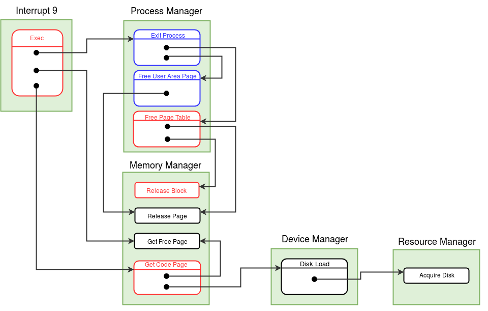
- Modifications of exec system call
- Get Code Page (function number = 5, memory manager module)
- Modification to the Free Page Table (function number = 4, process manager module)
- Release Block (function number = 4, Memory Manager Module)
- Implementation of Exception Handler
- Modification to the Boot Module
1) Don't allocate memory pages for heap. Instead, invalidate page table entries for heap.
2) Change the page allocation for code pages from previous stage. Invoke the Get Code Page
function for the first code block and update the page table entry for this first code page.
Invalidate rest of the code pages entries in the page table.
3) Initialize the disk map table of the process. The code page entries are set to the disk
block numbers from inode table of the program (program given as argument to exec). Initialize
rest of the entries to -1.
With these modifications, You have completed the final implementation of Exec system call.
The full algorithm is provided here.
1) Check the disk
map table entries of all the processes, if the given block number is present in
any entry and the corresponding page table entry is valid then return the memory page number.
Also increment the memory free list entry of that page. Memory Free list entry is incremented
as page is being shared by another process.
2) If the code page is not in memory, then invoke Get Free Page function in the memory manager module to allocate a new
page.
3) Load the disk block to the newly acquired memory page by invoking the Disk Load
function of the device manager module.
4) Return the memory page number to which the code block has been loaded.
1) Go through the heap and stack entries in the disk map table of the process with
given PID. If any valid entries are found, invoke the Release Block function in the memory manager module.
2) Invalidate all the entries of the disk map table.
1) Decrement the count of the disk block number in the memory copy of the Disk Free List.
2) Return to the caller.
Note : Get Code Page, Free Page Table
and Release Block functions implemented above are final versions. They will not
require modification in later stages.
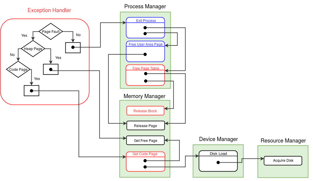
1) Set the MODE FLAG to -1 in the process
table of the current process, indicating in exception handler.
2) Switch to the kernel stack and backup the register context and push EIP onto the stack.
3) If the cause of the exception is other than page fault (EC is not equal to 0) or if the
user stack is full (when userSP is PTLR*512-1, the return address can't be pushed onto the
stack), then print a meaningful error message. Then invoke the Exit Process function
to halt the process and invoke the scheduler.
4) If page fault is caused due to a code page, then get the code block number to be loaded
from the disk map
table. For this block, invoke the Get Code Page function present in the memory manager module. Update the page table entry for this code page,
set the page number to memory page obtained from Get Code Page function and auxiliary
information to "1100".
5) If page fault is caused due to a heap page, then invoke the Get Free Page function of the memory manager module twice to allocate two memory pages for the heap. Update
the page table entry for these heap pages, set the page numbers to the memory pages obtained from
Get Free Page function and set auxiliary information to "1110".
6) Reset the MODE FLAG to 0. Pop EIP from the stack and restore the register context.
7) Change to the user stack. Increment the stack pointer, store the EIP value onto the
location pointed to by SP and return to the user mode. (Address translations needs to be done on the SP to find the stack address to which EIP is to be stored)
The Exception handler implementation given above is final. The full algorithm is given here.
Initialize the disk map table entries for the INIT process. Load the Disk Free List from the disk block 2 to the memory page 61. (See disk and memory organization here.)
Making things work
Compile and load the modified and newly written files into the disk using the XFS-interface.
-
Q1. Does EPN always equal to the
logical page number of EIP?
No. Page fault can occur in two situations. One possibility is during insturction fetch - if the instruction pointer points to an invalid page. In this case, the missing virtual page number (EPN) corresponds to the logical page number of the EIP. The second possibility is during instruction execution when an operand fetch/memory write accesses a page that is not loaded. In this case EPN will indicate the page number of the missing page, and not the logical page number corresponding to EIP value.
-
Q2. Why does the exception handler
terminate the process when the userSP value is PTLR*512-1 ?
The XSM machine doesn't push the return address into the user stack when the exception occurs, instead it stores the address in the EIP register. Hence, for the exception handler to return to the instruction which caused the exception, the EIP register value must be pushed onto the top of the user stack of the program. However, when the application's stack is full (userSP = PTLR*512-1), there is no stack space left to place the return address and the only sensible action for the OS is to terminate the process.
-
Q2. Why does the exception handler
save the contents of the EIP register immediately into the kernel stack upon entry into
the exception handler?
The execption handler may block for a disk read and invoke the scheduler during it's course of execution. The value of the EIP register must be stored before scheduling other processes as the current value will be overwritten by the machine if an exception occurs in another application that is scheduled in this way.
Assignment 1: Write an ExpL program to implement a linked list. Your program should first read an integer N, then read N intergers from console and store them in the linked list and print the linked list to the console. Run this program using shell version-I of stage 17.
Assignment 2: Use the XSM debugger to dump the contents of the Exception Flag registers upon entry into the Exception Handler. Also, print out the contents of the Disk Map Table and the Page Table after the Get Code Page function (inside the Memory Manager module).
Close
-
Final Stages:
Stage 20-Stage 27 are the final stages of the project where you will implement all the system calls stipulated in the ABI documentation. Typically 5-6 weeks will be needed to complete these stages. At the end of the twentieth stage, basic system calls for process creation and termination – Fork, Exec and Exit will be completed. The next two stages take up system calls implementing signals and semaphores. The next three stages address the implementation of the file system. The subsequent stages add multi-user support and virtual memory support. (An advanced stage (Stage 28) describing how the OS can be ported to a two-core extension of the XSM machine has been added subsequently.)
In this stage, you will learn how to create a new process using the fork system call and how to terminate a process using the exit system call.
Fork System Call
The Fork system call spawns a new process. The new process and the process which invoked fork have a child-parent relationship. The child process will be allocated a different PID and a new address space. Hence, the child process will have a different process table and page table. However, the child and the parent will share the code and heap regions of the address space. The child will be allocated two new stack pages and a new user area page.
The process table of the child is initialized with the same values of the parent except for the values of TICK, PID, PPID, USER AREA PAGE NUMBER, KERNEL STACK POINTER, INPUT BUFFER, MODE FLAG, PTBR and PTLR. The contents of the stack of the parent are copied into the new stack pages allocated for the child. The contents of the per process resource table in the user area page of the parent process is copied to the child process. However, the contents of the parent's kernel stack are not copied to the child, and the kernel stack of the child is set to empty (that is, KPTR field in the process table entry of the child is set to 0.)
Fork system call returns to the the parent process. The parent resumes execution from the next instruction following the INT instruction invoking fork. Upon successful completion, fork returns the PID of the child process to parent process.
After completion of fork, the child process will be ready for execution and will be in the CREATED state. When the child process is scheduled (by the scheduler) to run for the first time, it will start its execution from the immediate instruction after the call to fork. The return value of fork to the child process is zero.
We have already noted that the child process shares the heap and code pages with the parent process, whereas new memory pages are allocated for user stack of the child. The contents of the parent's user stack pages are copied to the user stack of the child process. ExpL compiler allocates local variables, global variables and arrays of primitive data types (int, string) of a process in the stack. Since the parent and child processes have different memory pages for the user stack, they resume after fork with separate private copies of these variables, with the same values. Since the stack page is not shared between the parent and the child, subsequent modifications to these variables by either parent or the child will not be visible to the other.
The Alloc() function of eXpOS library allocates memory from the heap region of a process. Hence memory allocated by Alloc() to store objects referenced by variables of user defined types in an ExpL program will be allocated in the heap. As heap pages are shared by the parent and the child, both processes share the memory allocated using Alloc(). Thus, if the parent had allocated memory using the Alloc() function and attached it to a variable of some user defined type before fork, the copies of the variables in both the parent and the child store the address of the same shared memory.
Since the Parent and child processes can concurrently access/modify the heap pages, they need support from the OS to synchronize access to the shared heap memory. eXpOS provides support for such synchronization through systems calls for semaphores and signal handling. These will be discussed in later stages. Even though, code and library pages are shared among parent and child processes, synchronization is not required for these pages as their access is read only.
Note: There is a subtility to be noted here. It can happen that the kernel has not allocated any heap pages for the parent process at the time when it invoked Fork. This is because heap pages are allocated inside the exception handler when a process generates a page fault exeception while trying to access the heap. Thus a process could invoke fork before any heap pages were allocated to it. However, the eXpOS sharing semantics requires that the parent and the child shares their heap pages. Hence, to satisfy the heap sharing semantics, the OS needs to ensure during Fork that the parent is allocated its heap pages and these pages are shared with the child.
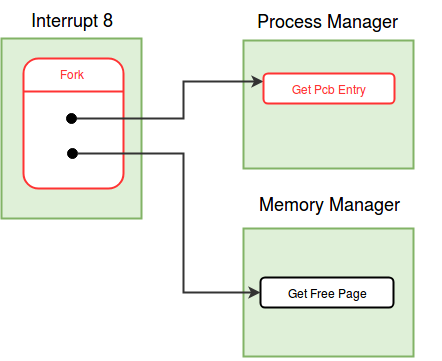
High level ExpL programs can invoke fork system call using the library interface function exposcall. Fork has system call number 8 and it is implemented in the interrupt routine 8. Fork does not take any arguments. Follow the description below to implement the fork system call.
Read the description of various entries of process table before proceeding further.
- The first action to perform in the fork system call is to set the MODE FLAG to the system call number and switch to the kernel stack. To get a new PID for the child process, invoke the Get Pcb Entry function from the process manager module. Get Pcb Entry returns the index of the new process table allocated for the child. This index is saved as the PID of the child. As there are only 16 process tables present in the memory, maximum 16 processes can run simultaneously. If a free process table is not available, Get Pcb Entry returns -1. In such case, store -1 as the return value in the stack, reset the MODE FLAG (to 0), switch to user stack and return to the user mode from the fork system call. When PID is available, proceed with the fork system call.
- If the heap pages are not allocated for the parent process, allocate heap pages by invoking the Get Free Page function of the memory manager module and set the page table entries for the heap pages of the parent process to the pages acquired.
- The child process requires new memory pages for stack (two) and user area page (one). To allocate a memory page, invoke the Get Free Page function of the memory manager module.
- The next step in the fork system call is initialization of the process table for the child process. Copy the USERID field from the process table of the parent to the child process, as the user (currently logged in) will be same for both child and parent. (We will discuss USERID later when we add multi-user support to eXpOS.) Similarly, copy the SWAP FLAG and the USER AREA SWAP STATUS fields. (These fields will be discussed later, when we discuss swapping out processes from memory to the disk.) INODE INDEX for the child and the parent processes will be same, as both of them run the same program. UPTR field should also be copied from the parent process. As mentioned earlier, content of the user stack is same for both of them, so when both of the processes resume execution in user mode, the value of SP must be the same.
- Set the MODE FLAG, KPTR and TICK fields of the child process to 0. MODE FLAG, KPTR are set to zero as the child process starts its execution from the user mode. The TICK field keep track of how long a process has been running in memory and should be initialized to 0, when a process is created. (The TICK field will be used later to decide which process must be swapped out of memory when memory is short. The strategy will be to swap out that process which had been in memory for the longest time). PID of the parent is stored in the PPID field of the process table of the child. STATE of the child process is set to CREATED. Store the new memory page number obtained for user area page in the USER AREA PAGE NUMBER field in the process table of the child proces. PID, PTBR and PTLR fields of the child process are already initialized in the Get Pcb Entry function. It is not required to initialize INPUT BUFFER.
- The per-process resource table has details about the open instances of the files and the semaphores currently acquired by the process. Child process shares the files and the semaphores opened by the parent process. Hence we need to copy the entries of the per-process resource table of the parent to the child. We will discuss files and semaphores in later stages. (There is a little bit more book keeping work associated with files and semaphores. Since we have not added files or semaphores so far to the OS, we will skip this work for the time being and complete the pending tasks in later stages).
- Copy the per-process disk map table of the parent to the child. This will ensure that the disk block numbers of the code pages of the parent process are copied to the child. Further, if the parent has swapped out heap pages, those will be shared by the child. (This will be explained in detail in a later stage). The eXpOS design guarentees that the stack pages and the user area page of a process will not be swapped at the time when it invokes the fork system call. Hence the disk map table entries of the parent process corresponding to the stack and user area pages will be invalid, and these entries of the child too must be set to invalid.
- Initialize the page table of the child process. As heap, code and library pages are shared by the parent process and the child process, copy these entries (page number and auxiliary information) form the page table of the parent to the child. For each page shared, increment the corresponding share count in the memory free list (why do we do need to do this?). Initialize the stack page entries in the page table with the new memory page numbers obtained earlier. Note that the auxiliary information for the stack pages is same for both parent and child (why?). Copy content of the user stack pages of the parent to the user stack pages of the child word by word.
- Store the value in the BP register on top of the kernel stack of child process. This value will be used to initialize the BP register of the child process by the scheduler when the child is scheduled for the first time.
- Set up return values in the user stacks of the parent and the child processes. Store the PID of the child process as return value to the parent and 0 as the return values to the child. Reset the MODE FLAG of the parent process. Switch to the user stack of the parent process and return to the user mode.
The complete version of the algorithm for the fork system call is provided here.
Get Pcb Entry (function number = 1, Process Manager Module)
The Get Pcb Entry function in the process manager, finds out a free process table entry and returns the index of it to the caller. If no process table entry is free, it returns -1. A free process table entry (STATE field is set to TERMINATED) can be found out by looping through all process table entries. Initialize the PID to the index of the free entry. Set the STATE to ALLOCATED. Initialize PTBR to the starting address of the page table for that process (obtained using index) and PTLR to 10. Return the index to the caller.
Note :The implementation of above Get Pcb Entry
module function is final version.
Modifications to Scheduler module
The context-switch (scheduler) module is modified in this stage. The BP register of the child has to be initiazed by the scheduler for the first time as child is in created state. Refer to the detailed schedular algorithm here.
- When the process is in created state, add folllowing steps before switching to user stack.
- Store the value in the first word of the kernel stack to the BP register.
Exit System Call
At the end of every process, exit system call is invoked to terminate the process. In the previous stages, we had already implemented the exit system call. Now, we will change the exit system call to invoke the module function Exit Process to terminate the process.
Exit system call has to update/clear the OS data structures of the terminating process and detach the memory pages allocated to the process from its address space. The page table entries are invalidated. There may be other processes waiting for this process to terminate. Exit system call must wake up these processes. (Currently, processes do not wait, we will see this in the next stage.) Exit has to close the files and release the semaphores acquired by the process. Per-process resource table has to be invalidated. Finally, Exit has to set the state of the process to TERMINATED. These tasks are done by invoking the Exit Process function of the process manager module.
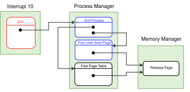
Exit system call has a system call number 10 and is implemented in the interrupt routine 10. Follow the description given below to implement the exit system call.
- Exit system call first sets the MODE FLAG to the system call number and switches to the kernal stack.
- It then invokes the Exit Process function present in the process manager module. Finally, Exit system call invokes the scheduler to schedule other processes.
Note :With above changes implementation of exit system
call is complete. The algorithm for exit system call is given here.
Modifications to the Boot module
Load interrupt routine 8 from disk to memory.
Making things workCompile and load interrupt routine 8, interrupt routine 10, module 2, module 5 into the disk using the XFS-interface.
-
Q1. How does eXpOS prevent a program
running in user mode from writing to the library and code pages?
In the page table of every process, pages of a process have auxiliary information associated with them. Auxiliary information consists of 4 bits of which third bit is write bit. If write bit is set to 1 for a page, then the process (to which the page belongs) has permission to write to the corresponding page. When write bit is set to 0, the page has read only access. So the process can not modify the content of the page. For every process, write bit is set to 0 for library and code pages while initializing page table. When a process tries to write to a page for which write bit is 0, XSM machine raises illegal memory access exception. Refer about auxiliary information here.
-
Q2. Where does ExpL allocate memory
for variables of user defined data type?
Variables of user defined data type are allocated memory in stack, same as any variable of primitive data type. Every variable in ExpL is allocated one word memory in stack. Variable of primitive data type saves actual data in the word that is allocated to it, but variables of user defined data type stores the starting address of the object. Alloc() library function allocates memory for an object in heap and returns the starting address. This return address is stored in the stack for corresponding variable.
-
Q3. Upon completion of the fork
system call, the parent and the child will contain the same return IP address on the
top of the user stack. The value of the user stack pointer (UPTR) will also be the same
for both the processes. When the fork sytem call returns to user mode (using the IRET
instruction) which process executes first - parent or child? why?
Fork system call returns to the parent process. IRET sets the value of IP register to the return address at the top of the stack, pointed to by the SP register. The machine translates the logical SP to physical SP using the page table pointed to by the PTBR register, which points to the page table of the parent. Subsequent instruction fetch cycles continue to proceed by translating the value of IP using the PTBR value, which points to the page table of the parent process. The parent process continues execution till a context switch occurs.
-
Q4.
What would go wrong if the Get Pcb Entry function sets the state
of a newly allocated PCB entry to CREATED instead of ALLOCATED?
The fork system call which invokes the Get Pcb Entry function for the child process might block before completing process creation (if the Get Free Page function finds no free page in memory and invokes the scheduler). In such case, the scheduler must not try to run the new process as its creation is not complete.
-
Q5.
When there is a page fault for a heap page, the exception
handler which you have completed in stage 19 allocates both the heap pages for the process. Suppose you modify the exception handler to allocate only one
heap page corresponding to the page requested (deferring the allocation of
the second page till another exception occurs), what modification
would be needed to your Fork system call code?
eXpOS semantics requires that the parent and the child share the heap. Hence, if the parent did not have two heap pages already allocated before Fork, the pages must be allocated at the time of Fork and shared with the child. An alternate approach would be to share only the presently allocated heap page (if any) of the parent with the child and wait for a page fault in either of the processes to allocate the other page. However, in this case, care must be taken to ensure that the same page is shared between the parent and the child when one of them is allocated a heap page.
Note :When all processes except IDLE are TERMINATED, our
present OS will repeatedly schedule IDLE and thus will be in an infinite loop. Hence you will
have to Use Ctrl+C to terminate the machine. We will ensure graceful shutdown from the next
stage.
Assignment 1: Write two ExpL programs even.expl and odd.expl to print the first 100 even and odd numbers respectively. Write another ExpL program that first creates a child process using Fork. Then, the parent process shall use the exec system call to execute even.xsm and the child shall execute odd.xsm. Load this program as the init program.
Assignment 2: Write an ExpL program which creates linked list of the first 100 numbers. The program then forks to create a child so that the parent and the child has separate pointers to the head of the shared linked list. Now, the child prints the 1st, 3rd, 5th, 7th... etc. entries of the list whereas the parent prints the 2nd, 4th, 6th, 8th....etc. entries of the list. Eventually all numbers will be printed, but in some arbitrary order (why?). The program is given here. Try to read and understand the program before running it. Run the program as the INIT program. In the next stages, we will see how to use the sychronization primitives of the OS to modify the above program so that the numbers are printed out in sequential order.
Close
In this stage, we will add support for process synchronization using Wait and Signal system calls to eXpOS. With the help of these system calls, we will design a more advanced shell program. We will also implement Getpid and Getppid system calls.
When a process executes the Wait system call, its execution is suspended till the process whose PID is given as argument to Wait terminates or executes the Signal system call. The process that enters Wait sets its state to WAIT_PROCESS and invokes the scheduler.
A process executes the Signal system call to wake up all the processes waiting for it. If a process terminates without invoking Signal, then Exit system call voluntarily wakes up all the processes waiting for it.
When several processes running concurrently share a resource (shared memory or file) it is necessary to synchronize access to the shared resource to avoid data inconsistency. Wait and Signal form one pair of primitives that help to achieve synchronization. In general, synchronization primitives help two co-operating processes to ensure that one process stops execution at certain program point, and waits for the other to issue a signal, before continuing execution.
To understand how Wait and Signal help for process synchronization, assume that two processes (say A and B) executing concurrently share a resource. When process A issues the Wait system call with the PID of process B, it intends to wait until process B signals or terminates. When process B is done with the resource, it can invoke the Signal system call to wake up process A (and all other processes waiting for process B). Thus, Signal and Wait can ensure that process A is allowed to access the resource only after process B permits process A to do so.
In the above example suppose process B had finished using the shared resource and had executed Signal system call before process A executed Wait system call, then process A will wait for process B to issue another signal. Hence if process B does not issue another signal, then process A will resume execution only after process B terminates. The issue here is that, although the OS acts on the occurance of a signal immediately, it never records the occurance of the signal for the future. In other words, Signals are memoryless. A more advanced synchronization primitive that has a state variable associated with it - namely the semaphore - will be added to the OS in the next stage.
When a process issues the Exit system call, all processes waiting for it must be awakened. We will modify the Exit Process function in the process manager module to wake up all processes waiting for the terminating process. However, there is one special case to handle here. The Exit Process function is invoked by the Exec system call as well. In this case, the process waiting for the current process must not be woken up (why?). The implementation details will be explained below.
Finally, when a process Exits, all its child processes become orphan processes and their PPID field is set to -1 in the module function Exit Process. Here too, if Exit Process in invoked from the Exec system call, the children must not become orphans.
Shell Program
The Shell is a user program that implements an interactive user interface for the OS. In the present stage, we will run the shell as the INIT program, so that the shell will interact with the user.
The shell asks you to enter a string (called a command). If the string entered is "Shutdown", the program executes the Shutdown system call to halt the OS. Otherwise, the shell program forks and create a child process. The parent process then waits for the child to exit using the Wait system call. The child process will try to execute the command (that is, execute the file with name command.) If no such file exists, Exec fails and the child prints "BAD COMMAND" and exits. Otherwise, the command file will be executed. In either case, upon completion of the child process, the parent process wakes up. The parent then goes on to ask the user for the next command.
Implementation of Interrupt routine 11
The system calls Wait, Signal, Getpid and Getppid are all implemented in the interrupt routine 11. Each system call has a different system call number.
- At the beginning of interrupt routine 11, extract the system call number from the user stack and switch to the kernel stack.
- Implement system calls according to the system call number extracted from above step. Steps to implement each system call are explained below.
- Change back to the user stack and return to the user mode.
The system call numbers for Getpid, Getppid, Wait and Signal are 11, 12, 13 and 14 respectively. From ExpL program, these system calls are invoked using exposcall function.
Wait System Call
Wait system call takes PID of a process (for which the given process will wait) as an argument.
- Change the MODE FLAG in the process table to the system call number.
- Extract the PID from the user stack. Check the valid conditions for argument. A process should not wait for itself or a TERMINATED process. The argument PID should be in valid range (what is the valid range?). If any of the above conditons are not satisfying, return to the user mode with -1 stored as return value indicating failure. At any point of return to user, remember to reset the MODE FLAG and change the stack to user stack.
- If all valid conditions are satisfied then proceed as follows. Change the state of the current process from RUNNING to the tuple (WAIT_PROCESS, argument PID) in the process table. Note that the STATE field in the process table is a tuple (allocated 2 words).
- Invoke the scheduler to schedule other processes.
- Reset the MODE FLAG in the process table of the current process.
Store 0 in the user stack as return value and return to the calling program.
/*The following step is executed only when the scheduler runs this process again, which in turn happens only when the state of the process becomes READY again.*/
Signal System Call
Signal system call does not have any arguments.
- Set the MODE FLAG in the process table to the signal system call number.
- Loop through all process table entries, if there is a process with STATE as tuple (WAIT_PROCESS, current process PID) then change the STATE field to READY.
- Reset the MODE FLAG to 0 in the process table and store 0 as return value in the user stack.
- Loop through the process table of all processes and change the state to READY for the processes whose state is tuple (WAIT_PROCESS, current PID). Also if the PPID of a process is PID of current process, then invalidate PPID field to -1.
-
Q1. Does the eXpOS guarantees that
two processes will not wait for each other i.e. circular wait will not happen?
No. The present eXpOS does not provide any functionality to avoid circular wait. It is the responsiblity of the user program to make sure that such conditions will not occur.
Getpid and Getppid System Calls
Getpid and Getppid system calls returns the PID of the current process and the PID of the parent process of the current process respectively to the user program. Implement both these system calls in interrupt routine 11.
Note :The system calls implemented above are final and will not change later.
See algorithms for Wait/Signal
and Getpid/Getppid.
Modifications to Exit Process Function (function number = 3, Process Manager Module)
Exit Process function is modified so that it wakes up all the processes waiting for the current process. Similarly, the children of the process are set as orphan processes by changing PPID field of child processes to -1. But when the Exit Process function is invoked from Exec system call, the process is actually not terminating as the new program is being overlayed in the same address space and is executed with the same PID. when Exit Process is invoked from Exec system call, it should not wake up the processes waiting for the current process and also should not set the children as orphan processes. Check the MODE FLAG in the process table of the current process to find out from which system call Exit Process function is invoked.
If MODE FLAG field in the process table has system call number not equal to 9 (Exec) implement below steps.
Note :The function implemented above is final and will not change later.
To ensure graceful termination of the system we will write Shutdown system call with just a HALT instruction. Shutdown system call is implemented in interrupt routine 15. Create an xsm file with just the HALT instruction and load this file as interrupt routine 15. From this stage onwards, we will use a new version of Shell as our init program. This Shell version will invoke Shutdown system call to halt the system.
In later stages, when a file system is added to the OS, the file system data will be loaded to the memory and modified, while the OS is running. The Shutdown system call will be re-written so that it commits the changes to the file system data to the disk before the machine halts.
Modifications to boot module
Load interrupt routine 11 and interrupt routine 15 from disk to memory. See disk and memory organization here.
Making things work
Compile and load the newly written/modified files to the disk using XFS-interface.
Assignment 2: Write an ExpL program 'pid.expl' which invokes Getpid system call and prints the pid. Write another ExpL program which invokes Fork system call three times back to back. Then, the program shall use Exec system call to execute pid.xsm file. Run this program using the shell.
Close
In this stage, we will add support for semaphores to the OS. Semaphores are primitives that allow concurrent processes to handle the critical section problem. A typical instance of the critical section problem occurs when a set of processes share memory or files. Here it is likely to be necessary to ensure that the processes do not access the shared data (or file) simultaneously to ensure data consistency. eXpOS provides binary semaphores which can be used by user programs (ExpL programs) to synchronize the access to the shared resources so that data inconsistency will not occur.
There are four actions related to semaphores that a process can perform. Below are the actions
along with the corresponding eXpOS system calls -
1) Acquiring a semaphore - Semget system call
2) Releasing a semaphore - Semrelease
system call
3) Locking a semaphore - SemLock system call
4) Unlocking a
semaphore - SemUnLock system call
To use a semaphore, first a process has to acquire a semaphore. When a process forks, the semaphores currently acquired by a process is shared between the child and the parent. A process can lock and unlock a semaphore only after acquiring the semaphore. The process can lock the semaphore when it needs to enter into the critical section. After exiting from the critical section, the process unlocks the semaphore allowing other processes (with which the semaphore is shared) to enter the critical section. After the use of a semaphore is finished, a process can detach the semaphore by releasing the semaphore.
A process maintains record of the semaphores acquired by it in its per-process resource table. eXpOS uses the data structure, semaphore table to manage semaphores. Semaphore table is a global data structure which is used to store details of semaphores currently used by all the processes. The Semaphore table has 32 (MAX_SEM_COUNT) entries. This means that only 32 semaphores can be used by all the processes in the system at a time. Each entry in the semaphore table occupies four words of which the last two are currently unused. For each semaphore, the PROCESS COUNT field in it's semaphore table entry keeps track of the number of processes currently sharing the semaphore. If a process locks the semaphore, the LOCKING PID field is set to the PID of that process. LOCKING PID is set to -1 when the semaphore is not locked by any process. An invalid semaphore table entry is indicated by PROCESS COUNT equal to 0. The SPL constant SEMAPHORE_TABLE gives the starting address of the semaphore table in the memory. See semaphore table for more details.
The per-process resource table of each process keeps track of the resources (semaphores and files) currently used by the process. The per-process resource table is stored in the last 16 words of the user area page of a process. Per-process resource table can store details of at most eight resources at a time. Hence the total number of semaphores and files acquired by a process at a time is at most eight. Each per process resource table entry contains two words. The first field, called the Resource Identifier field, indicates whether the entry corresponds to a file or a semaphore. For representing the resource as a file, the SPL constant FILE (0) is used and for semaphore, the SPL constant SEMAPHORE (1) is used. The second field stores the index of the semaphore table entry if the resource is a semaphore. (If the resource is a file, an index to the open file table entry will be stored - we will see this in later stages.) See the description of per-process resource table for details.
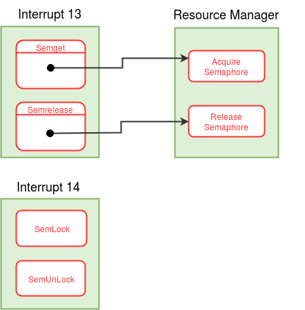
Implementation of Interrupt routine 13
The system calls Semget and Semrelease are implemented in the interrupt routine 13. Semget and Semrelease has system call numbers 17 and 18 respectively.
- Extract the system call number from the user stack and switch to the kernel stack.
- Implement system calls Semget and Semrelease according to the system call number extracted from above step. Steps to implement these system calls are explained below.
- Change back to the user stack and return to the user mode.
- Semget System Call
- Semrelease System Call
- Acquire Semaphore (function number = 6, resource manager module)
- Release Semaphore (function number = 7, resource manager module)
Semget system call is used to acquire a new semaphore. Semget finds a free entry in the per-process resource table. Semget then creates a new entry in the semaphore table by invoking the Acquire Semaphore function of resource manager module. The index of the semaphore table entry returned by Acquire Semaphore function is stored in the free entry of per-process resource table of the process. Finally, Semget system call returns the index of newly created entry in the per-process resource table as semaphore descriptor (SEMID).
Implement Semget system call using the detailed algorithm provided here.
Semrelease system call takes semaphore desciptor (SEMID) as argument from user program.Semrelease system call is used to detach a semaphore from the process. Semrelease releases the acquired semaphore and wakes up all the processes waiting for the semaphore by invoking the Release Semaphore function of resource manager module. Semrelease also invalidates the per-process resource table entry corresponding to the SEMID given as an argument.
Implement Semrelease system call using the detailed algorithm provided here.
Note : If any semaphore is not released by a process
during execution using Semrelease system call, then the semaphore is released at the
time of termination of the process in Exit system call.
Acquire Semaphore function takes PID of the current process as argument. Acquire Semaphore finds a free entry in the semaphore table and sets the PROCESS COUNT to 1 in that entry. Finally, Acquire Semaphore returns the index of that free entry of semaphore table.
Implement Acquire Semaphore function using the detailed algorithm provided in resource manager module link above.
Release Semaphore function takes a semaphore index (SEMID) and PID of a process as arguments. If the semaphore to be released is locked by current process, then Release Semaphore function unlocks the semaphore and wakes up all the processes waiting for this semaphore. Release Semaphore function finally decrements the PROCESS COUNT of the semaphore in its corresponding semaphore table entry.
Implement Release Semaphore function using the detailed algorithm provided in resource manager module link above.
The system calls SemLock and SemUnLock are implemented in the interrupt routine 14. SemLock and SemUnLock has system call numbers 19 and 20 respectively.
- Extract the system call number from the user stack and switch to the kernel stack.
- Implement system calls SemLock and SemUnLock according to the system call number extracted from above step. Steps to implement these system calls are explained below.
- Change back to the user stack and return to the user mode.
- SemLock System Call
- SemUnLock System Call
SemLock system call takes a semaphore desciptor (SEMID) as an argument from user program. A process locks the semaphore it is sharing using the SemLock system call. If the requested semaphore is currently locked by some other process, the current process blocks its execution by changing its STATE to the tuple (WAIT_SEMAPHORE, semaphore table index of requested semaphore) until the requested semaphore is unlocked. When the semaphore is unlocked, then STATE of the current process is made READY (by the process which has unlocked the semaphore). When the current process is scheduled and the semaphore is still unlocked the current process locks the semaphore by changing the LOCKING PID in the semaphore table entry to the PID of the current process. When the process is scheduled but finds that the semaphore is locked by some other process, current process again waits in the busy loop until the requested semaphore is unlocked.
Implement SemLock system call using the detailed algorithm provided here.
SemUnLock system call takes a semaphore desciptor (SEMID) as argument. A process invokes SemUnLock system call to unlock the semaphore. SemUnLock invalidates the LOCKING PID field (store -1) in the semaphore table entry for the semaphore. All the processes waiting for the semaphore are made READY for execution.
Implement SemUnLock system call using the detailed algorithm provided here.
Note : The implementation of Semget, Semrelease,
SemLock, SemUnLock system calls and Acquire Semaphore, Release
Semaphore module functions are final.
Modifications to Fork system call
In this stage, Fork is modified to update the semaphore table for the semaphores acquired by the parent process. When a process forks, the semaphores acquired by the parent process are now shared between parent and child. To reflect this change, PROCESS COUNT field is incremented by one in the semaphore table entry for every semphore shared between parent and child. Refer algorithm for fork system call.
- While copying the per-process resource table of parent to the child process do following -
- If the resource is semaphore (check the Resource Identifier field in the per-process resource table), then using the sempahore table index, increment the PROCESS COUNT field in the semaphore table entry.
Modifications to Free User Area Page (function number = 2, process manager module)
The user area page of every process contains the per-process resource table in the last 16 words. When a process terminates, all the semaphores the process has acquired (and haven't released explicitly) have to be released. This is done in the Free User Area Page function. The Release Semaphore function of resource manager module is invoked for every valid semaphore in the per-process resource table of the process.
- For each entry in the per-process resource table of the process do following -
- If the resource is valid and is semaphore (check the Resource Identifier field in the per-process resource table), then invoke Release Semaphore function of resource manager module.
Note : Fork system call and Free User
Area page function will be further modified in later stages for the file resources.
Modifications to boot module
- Initialize the semaphore table by setting PROCESS COUNT to 0 and LOCKING PID to -1 for all entries.
- Load interrupt routine 13 and 14 from the disk to the memory. See memory organisation.
Making things work
Compile and load the newly written/modified files to the disk using XFS-interface.
-
Q1.When a process waiting for a
sempahore is scheduled again after the sempahore is unlocked, is it possible that the
process finds the sempahore still locked?
Yes, it is possible. As some other process waiting for the semaphore could be scheduled before the current process and could have locked the semaphore. In this case the present process finds the semaphore locked again and has to wait in a busy loop until the required sempahore is unlocked.
-
Q2.A process first locks a semaphore
using SemLock system call and then forks to create a child. As the semaphore is now
shared between child and parent, what will be locking status for the semaphore?
The sempahore will still be locked by the parent process. In Fork system call, the PROCESS COUNT in the semaphore table is incremented by one but LOCKING PID field is left untouched.
Assignment 2: The ExpL programs given here describes a parent.expl program and a child.expl program. The parent.xsm program will create 8 child processes by invoking Fork 3 times. Each of the child processes will print the process ID (PID) and then, invokes the Exec system call to execute the program "child.xsm". The child.xsm program stores numbers from PID*100 to PID*100 + 9 onto a linked list and prints them to the console (each child process will have a seperate heap as the Exec system call alocates a seperate heap for each process). Compile the programs given in the link above and execute the parent program (parent.xsm) using the shell. The program must print all numbers from PID*100 to PID*100+9, where PID = 2 to 9, but not necessarily in sequential order. Also, calculate the maximum memory usage, number of disk access and number of context switches (by modifying the OS Kernel code).
Assignment 3: The two ExpL programs given here perform merge sort in two different ways. The first one is done in a sequential manner and the second one, in a concurrent approach. Values from 1 to 64 are stored in decreasing order in a linked list and are sorted using a recursive merge sort function. In the concurrent approach, the process is forked and the merge sort function is called recursively for the two sub-lists from the two child processes. Compile the programs given in the link above and execute each of them using the shell. The program must print values from 1 to 64 in a sorted manner. Also, calculate the maximum memory usage, number of contexts switches and the number of switches to KERNEL mode.
Close
In this stage, we will discuss how files are created and deleted by the application program with the help of file system calls Create and Delete. Shutdown system call will be modified in this stage.
Create system call creates an empty file with the name given as input. Create system call initializes the disk data structures with meta data related to the file. Inode table and root file are the disk data structures used to maintain permanent record of files. Delete system call deletes the record of the file with the given name from inode table and root file. Delete also releases the disk blocks occupied by the file to be deleted. The Shutdown system call is modified to commit the changes made by Create and Delete system calls in the memory copy of the disk data structures back into the disk.
Inode table and root file stores details of every eXpOS file stored in the disk. eXpOS allows at most MAX_FILE_NUM (60) files to be stored in the disk. Hence, both inode table and root file has MAX_FILE_NUM entries. The entry for a file in the inode table is identified by an index of its record in the inode table. For each file, the inode table entry and root file entry should have the same index. The disk data structures have to be loaded from the disk to the memory in order to use them while OS is running. The OS maintains the memory copy of the inode table in memory pages 59 and 60. Also the memory copy of root file is present in memory page 62. See memory organization for more details.
Interrupt routine 4
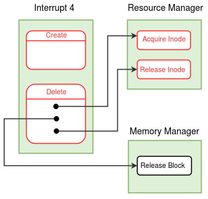
The system calls Create and Delete are implemented in the interrupt routine 4. Create and Delete have system call numbers 1 and 4 respectively. From ExpL programs, these system calls are called using exposcall function.
- Create system call
- Delete system call
- Acquire Inode (function number = 4, resource manager module )
- Release Inode (function number = 5, resource manager module )
Create system call takes filename and permission (integer 0 or 1) as arguments from the user program. As Create allows to create only data file, it is recommended to use .dat as extension for file names. Create finds a free entry (indicated by -1 in the FILE NAME field) in the inode table to store details related to the new file. The fields in the free inode table entry and corresponding root file entry are initialized with the meta-data of the new file.
The USERID field in the inode table is initialized to the USERID field from the process table of the current process. Hence, the user executing the Create system call becomes the owner of the file. The USERNAME field in the root file entry is initialized to the username corresponding to the USERID. The username can be obtained from memory copy of the user table with index as USERID. User table in the disk is initialized by the XFS-interface (during disk formatting) to create two users - kernel and root.
Implement Create system call using the detailed algorithm provided here.
Delete system call takes file name as an argument from the user program. A file can not be deleted if it is currently opened by one or more processes. Delete first acquires the lock on the file by invoking Acquire Inode function from resource manager module. Delete then invalidates the record of the file in entries of the inode table and root file. Also, the blocks allocated to the file are released. Finally, Delete releases the lock on file by invoking Release Inode function of the resource manager module.
There is one subtility involved in deleting a file. If any of the disk blocks of the deleted file are in the buffer cache, and if the buffer page is marked dirty, the OS will write back the buffer page into the disk block when another disk block needs to be brought into the same buffer page. However, such write back is unnecessary if the file is deleted (and can even be catastrophic- why?). Hence, Delete system call must clear the dirty bit (in the buffer table) of all the buffered disk blocks of the file.
Implement Delete system call using the detailed algorithm provided here.
Acquire Inode takes an inode index and PID of a process as arguments. To lock the inode (file), Acquire Inode first waits in a busy loop by changing state to (WAIT_FILE, inode index) until the file becomes free. After the inode becomes free and current process resumes execution, acquire inode checks whether the file is deleted from the system. (This check is necessary because, some other process may delete the file while the current process was waiting for the inode to be free.) Acquire Inode then locks the inode by setting LOCKING PID field in the file status table to the given PID.
Implement Acquire Inode function using the detailed algorithm given in the resource manager module link above.
Release Inode takes an inode index and PID of a process as arguments. Release Inode frees the inode (file) by invalidating the LOCKING PID field in the file status table. The function then wakes up the processes waiting for the file with given inode index by changing state of those processes to READY.
Implement Release Inode function using the detailed algorithm given in the resource manager module link above.
Note :The implementation of Create, Delete,
Acquire Inode and Release Inode are final.
Interrupt routine 15 (Shutdown system call)
Create and Delete system calls update the memory copies of Inode table, disk free list and root file. The changed data structures are not committed into the disk by these system calls. The disk update for these data structures are done during system shutdown.
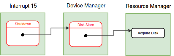
Interrupt routine 15 written in stage 21 contains just HALT instruction. In this stage, Shutdown system call is implemented in the interrupt routine 15. Shutdown system call has system call number 21 and it does not have any arguments.
- Shutdown system call
- Switch to the kernel stack and set the MODE FLAG in the process table to the system call number.
- Shutdown system call can be invoked only from the shell process of the root user. If the current process is not shell (PID in the process table is not equal to 1) or the current user is not root user (USERID in the process table is not equal to 1) then store -1 as return value, reset the MODE FLAG, change the stack to user stack and return to user mode.
- Commit the changes made in the memory copies of the inode table (along with user table), the root file and the disk free list by storing them back to the disk invoking the Disk Store function of device manager module. Refer to disk/memory organization for block and page numbers of these data structures. Finally, halt the system using the SPL statement halt.
- Disk Store (function number = 1, Device manager module)
Note :The implementation of the Shutdown system
call is not final. Implementation will change in later stages.
Disk Store function takes PID of a process, a page number and a block number as arguments. To store data into the disk, Disk Store first needs to lock the disk by invoking the Acquire Disk function of the resource manager module. After locking the disk, Disk Store updates the disk status table. Finally, Disk Store initiates the store operation for given page number and block number and waits in WAIT_DISK state until the store operation is complete. When store operation is completed, system raises the disk interrupt which makes this process READY again.
Implement Disk Store function using the detailed algorithm given in the device manager module link above.
Note :The implementation of Disk Store function
is final.
- Load interrupt routine 4 and root file from the disk to the memory. See the memory organization here.
- Initialize the file status table by setting LOCKING PID and FILE OPEN COUNT fields of all entries to -1.
- Initialize the buffer table by setting BLOCK NUMBER and LOCKING PID fields to -1 and DIRTY BIT to 0 in all entries.
- At present to simplify the implementation, we consider a single user system with only one user called root, USERID of root is 1. Hence, set the USERID field in the process table of INIT to 1. Later when INIT is forked, the USERID field is copied to the process table of the child process.
Making things work
Compile and load the newly written/modified files to the disk using XFS-interface.
-
Q1. What is the need for Delete
system call to lock the file before deleting it?
Locking the file in Delete system call makes sure that some other process will not be able to open the file or perform any other operation on the file during the deletion of the file.
Assignment 1: Write an ExpL program to take file name(string) and permission(integer) as input from the console and create a file with the provided input. (It is recommended to have .dat as extension for data files.) Run this program using shell. Using XFS-interface check if the entry for the file is created in inode table and root file.
Assignment 2: Write an ExpL program to take file name(string) as input from the console and delete a file with provided input. Run the program using shell. Using XFS-interface check if the entry for the file is deleted from inode table and root file. Check the program for different files- like files created using Create system call, files not present in disk and files loaded using XFS-interface having some data (eg- sample.dat used in stage 2).
Close
In this stage, we will understand the mechanism of opening and closing a file with the help of Open and Close system calls. We will also understand how contents of a file can be read by using Read system call. Fork system call and Free User Area Page function of process manager module are also modified in this stage.
Interrupt routine 5
The system calls Open and Close are implemented in the interrupt routine 5. Open and Close have system call numbers 2 and 3 respectively. From ExpL programs, these system calls are called using exposcall function.
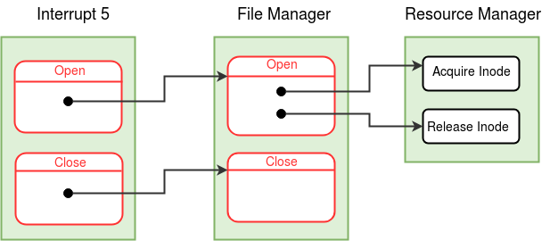
- Open system call
- Close system call
- Open (function number = 3, file manager module )
- Close (function number = 4, file manager module )
- Modifications to Fork system call
- While Copying the per-process resource table of parent to the child process do following -
- If the resource is a file (check the Resource Identifier field in the per-process resource table), then using the open file table index, increment the OPEN INSTANCE COUNT field in the open file table entry. /*The change in Fork system call to update the semaphore table, is already done in stage 22*/
- Modifications to Free User Area Page (function number = 2, process manager module )
- For each entry in the per-process resource table of the process, do following -
- If the resource is valid and is file (check the Resource Identifier field in the per-process resource table), then invoke the Close function of the file manager module. /*The change in the Free User Area Page to release the unrelased semaphores is already done in stage 22*/
Open system call takes a filename as an argument from the user program. To perform read/write operations on a file, a process must open the file first. Open system call creates a new open instance for the file and returns a file descriptor (index of the new per-process resource table entry created for the open instance). Further operations on the open instance are performed using this file descriptor. A process can open a file several times and each time a different open instance (and new descriptor) is created. The global data structure, Open file table keeps track of all the open file instances in the system. (A new entry is created in this table whenever the Open system call is invoked with any file name.) File status table is a global data structure that maintains an entry for every file in the system (not just opened files).
Open system call creates new entries for the file to be opened in the per-process resource table and the open file table. A process keeps track of an open instance by storing the index of the open file table entry of the instance in (the corresponding) resource table entry. When a file is opened, the OPEN INSTANCE COUNT in the open file table is set to 1 and seek position is initialized to the starting of the file (0).
Each time when a file is opened, the FILE OPEN COUNT in the file status table entry for the file is incremented by one. Open system call invokes Open function of file manager module to deal with global data structures - file status table and open file table. When a process executes a Fork system call, the open instances of files (and semaphores) created by the process are shared between the current process and its child. As an effect of Fork, the OPEN INSTANCE COUNT in the open file table entry corresponding to the open instance is incremented by one.
It is necessary not to be confused between FILE OPEN COUNT (in the file status table) and OPEN INSTANCE COUNT (in the open file table). The former keeps track of the global count of how many times Open system call has been invoked with each file in the system - that is the number of open instances of a file at a given point of time. This count is decremented each time when a Close is invoked on the file by any process. Each open instance could be further shared between multiple processes (via Fork). OPEN INSTANCE COUNT value of a particular open instance essentially keeps track of this "share count".
Implement Open system call using the detailed algorithm provided here.
When a process no longer needs to perform read/write operations on an open instance of a file, the open instance may be closed using the Close system call. Even if a process does not explicitly close an open instance by invoking Close system call, the open instance is closed at the termination of the process by Exit system call.
Close system call takes a file descriptor (index of the per-process resource table entry) as argument from the user program. Close system call invalidates the per-process resource table entry (corresponding to given file descriptor) by storing -1 in the Resource Identifier field. To decrement share count of the open instance in the open file table and update the file status table accordingly, Close function of file manager module is invoked by the Close system call.
Implement Close system call using the detailed algorithm provided here.
Open function is invoked by Open system call to update the file status table and the open file table when a file is opened. Open takes a file name as an argument. This function locates the inode index for the file in the inode table and locks the inode before proceeding further. Acquire Inode function of resource manager module is invoked to lock the file. Locking the file is necessary to make sure that no other process tries to delete the file concurrently. Open function creates a new entry in the open file table and returns the index of this entry to the caller. (Note that this index recieved as return value is stored in the per-process resource table entry by the Open system call.) All the fields of the open file table entry are initialized. In case the file is "root" file, INODE INDEX field is initialized to the INODE_ROOT (0). Open function increments the FILE OPEN COUNT field by one in the file status table entry for the file, except if the file is "root" file. (FILE OPEN COUNT is irrelevent for the root file as the root file is pre-loaded into the memory at boot time and can never be deleted.) The lock on the file is released by invoking Release Inode function of resource manager module before returning to the caller.
Implement Open function using the detailed algorithm given in the file manager module link above.
Close function is invoked by the Close system call to update the file status table and the open file table when a file is closed. Close takes an open file table index as argument. Close function decrements the share count (i.e OPEN INSTANCE COUNT field in the open file table entry) as the process no longer shares the open instance of the file. When the share count becomes zero, this indicates that all processes sharing that open instance of the file have closed the file. Hence, open file table entry corresponding to that open instance of the file is invalidated by setting the INODE INDEX field to -1 and the open count of the file (FILE OPEN COUNT field in file status table entry) is decremented.
Implement Close function using the detailed algorithm given in the file manager module link above.
There is a simple modification required to the Fork System call. When a process forks to create a child process, the file instances currently opened by the parent are now shared between child and parent. To reflect this change, the OPEN INSTANCE COUNT field in the open file table is incremented for each open file instance in the per-process resource table of parent process.
When a process terminates, all the files the process has opened (and haven't closed explicitly) have to be closed. This is done in the Free User Area page function. The Close function of the file manager module is invoked for every open file in the per-process resource table of the process.
Note :The implementation of Open,Close,
Fork system calls and Open, Close, Free User Area Page
functions are final.
Interrupt routine 6 (Read system call)
Interrupt routine 6 written in stage 16 reads data (words) only from the terminal. In this stage, Read system call is modified to read data from files. Read system call has system call number 7. From ExpL programs, Read system call is called using exposcall function.
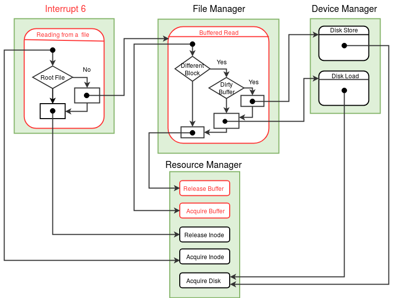
- Read system call
- Buffered Read (function number = 2, file manager module )
- Acquire Buffer (function number = 1, resource manager module )
- Release Buffer (function number = 2, resource manager module)
Read system call takes as input a file descriptor and the address of a word into which data should be read. Read system call locks the inode (corresponding to the file descriptor) at the beginning of the system call and releases the lock at the end of the system call. The functions Acquire Inode and Release Inode of resource manager module are used to lock and release the inode respectively.
Read system call reads the word at the position pointed to by the value of LSEEK (in the open file table entry) and stores it into the memory address provided as input. After reading the word from the file, LSEEK is incremented by one.
As file data is stored in the disk blocks allocated to the file, in order to read from position pointed to by LSEEK, the disk block containing the word pointed to by LSEEK has to be loaded first into the memory. eXpOS maintains a buffer cache (see memory organization)that can store up to four disk blocks in memory simultaneously. The cache pages are numbered 0,1,2 and 3 and are stored in memory pages 71, 72, 73 and 74. The simple caching scheme we user here is the following. If we want to bring disk block N into memory, the cache page N mod 4 will be used. Hence, if the disk block number to be loaded is - say 195 - then the cache page number to which the block will be noded is 3 and hence, the block will be loaded to page number 74. The functions Buffered Read and Buffered Write of the file manager module are designed to handle buffer management. Read invokes Buffered Read function to bring the required disk block into the memory buffer and read the word present at position LSEEK.
Reading from the root file does not require a buffer, as root file is already loaded into the memory at boot-time. Memory copy of the root file is present in memory page 62 and the start address of this page is denoted by the SPL constant ROOT_FILE. The word in the root file at LSEEK position is copied into the address provided. Note that the memory address provided as argument is a logical address, and as system call runs in kernel mode logical address should be translated to physical address before storing data.
Read system call needs to lock the resources - Inode (file), buffer and disk before using them. These are locked in the order 1) Inode 2) buffer and 3) disk and released in the reverse order. This order is also followed while writing to a file. Ordering of resource acquisition is imposed in order to avoid processes getting into circular wait for resources. Avoiding circular wait prevents deadlocks.
Implement Read system call using detailed algorithm provided here.
Buffered Read takes as input 1) a disk block number, 2) an offset value and 3) a physical memory address. The task of Buffered read is to read a word at position specified by the offset within the given disk block and store it into the given physical memory address. To read a word from a disk block, it has to be present in the memory. Memory buffer cache is used for this purpose. The disk block is loaded (if not loaded already) into the buffer page with buffer number given by formula - (disk block number%4).
To use a buffer page, it has to be locked first by invoking Acquire Buffer function of resource manager module. To load a disk block into a memory buffer page, Buffered Read invokes the function Disk Load of the device manager module. After loading the given disk block into the corresponding buffer, the word present at the given offset in the memory buffer is copied into the address given as argument.
The buffer page to which a disk block has to be loaded may contain some other disk block. In such case, if the buffer page has been modified earlier (dirty bit in the buffer table is set), the disk block present in the buffer has to be stored back into the disk before loading a new disk block. To store a disk block back into the disk, Buffered Read invokes Disk Store function of device manager module.
After completion of the read operation, Buffered Read unlocks the buffer page by invoking Release Buffer function of resource manager module. Now that the buffer is unlocked, other processes are allowed to use the buffer.
Implement Buffered Read function using the detailed algorithm given in the file manager module link above.
Acquire Buffer takes a buffer number and PID of a process as arguments. This function is invoked by the Buffered Read and Buffered Write functions of the file manager module to lock a buffer before its use. A process needs to acquire a buffer before accessing it to prevent data inconsistency that may arise if other processes are allowed to access the buffer concurrently.
Acquire Buffer locks a buffer by storing the given PID in the LOCKING PID field of the buffer table entry corresponding to the given buffer number. If the required buffer is locked by some other process (some other process has set the LOCKING PID), then the process with the given PID is blocked (STATE is changed to (WAIT_BUFFER, buffer number) in the process table). The process waits in the blocked state, until the required buffer is free. When the process which has acquired the buffer releases the buffer by invoking Release Buffer function (described next), the state of this blocked process is made READY and Acquire Buffer attempts to lock the buffer again.
Implement Acquire Buffer function using the detailed algorithm given in the resource manager module link above.
A process uses the Release Buffer function to release a buffer page that it has acquired earlier.
Release Buffer takes as input the number of a buffer page to be released and the PID of a process. Release Buffer function invalidates the LOCKING PID field (store -1) in the buffer table entry corresponding to the given buffer number. Release Buffer also wakes up all processes waiting for the buffer with given buffer number by changing the STATE in the process table from tuple (WAIT_BUFFER, buffer number) to READY.
Implement Release Buffer function using the detailed algorithm given in the resource manager module link above.
Note :The implementation of Read system
call and Buffered Read, Acquire Buffer, Release Buffer functions are
final.
Modifications to boot module
- Load interrupt routine 5 and module 3 from the disk to the memory. See the memory organization here.
- Initialize all entries of the open file table by setting INODE INDEX field to -1 and OPEN INSTANCE COUNT field to 0.
Making things work
Compile and load the newly written/modified files to the disk using XFS-interface.
Assignment 1: Write an ExpL program to take file name as input from the console, read the contents of the file and print to the console. Run this program using shell. Load external data files needed for the program using XFS-interface, as at present eXpOS does not support writing to a file. Check the program with following data files as input - 1) sample.dat from stage 2, 2) "numbers.dat" containing numbers 1 to 2047 separated by new line. (You may write a C program to generate the file "numbers.dat".)
Assignment 2: Run the program provided here using shell. Use data files from previous question as input. The program takes name of a data file as input and opens the file first. It then forks to create child process. The content of the file with shared open instance (shared LSEEK) will be printed to the terminal concurrently by parent and child. A semaphore is used to synchronize the use of the open instance between parent and child.
Close
In this stage, We will learn how contents of a file are modified using Write system call. Seek system call which is used to change the LSEEK position for a open instance is also implemented in this stage. Shutdown system call is modified to terminate all processes and store back the memory buffers which are modified during Write system call to the disk.
Interrupt routine 7 (Write system call)
Interrupt routine 7 written in stage 15, writes data (words) only to the terminal. In this stage, we will modify Write system call to write data into a file. Write system call has system call number 5. From ExpL programs, Write system call is called using exposcall function.
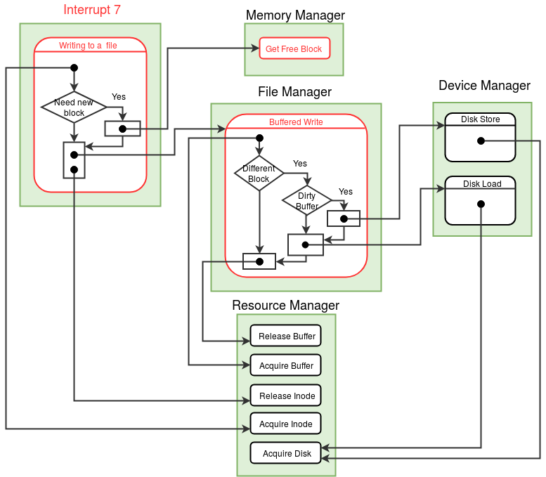
- Write system call
- Buffered Write (function number = 1, file manager module )
- Get Free Block (function number = 3, memory manager module )
Write system call takes as arguments 1) a file descriptor and 2) a word to be written into the file. Write system call locks the inode at the beginning of the system call and releases the lock at the end of the system call. The functions Acquire Inode and Release Inode of Resource Manager Module are used to lock and release inodes.
After acquiring the Inode, Write system call writes the given word to the file, at the offset determined by LSEEK (field in the open file table entry). Previously present data, if any, at the position determined by LSEEK is overwritten by the write operation. The maximum file size permitted by eXpOS is four disk blocks. Hence, Write fails if the LSEEK value exceeds 2047.
The Write system call finds the logical block number corresponding to the LSEEK position using the formula LSEEK / 512. LSEEK % 512 gives the offset position in the block to which data must be written into. For example, if the LSEEK value is 1024, then the block number will be 2 (third data block) and the offset is 0. The block numbers of the disk blocks that had been allocated for the file so far are stored in the inode table entry corresponding to the file.
In the above example, suppose that the file had been allocated three or more blocks earlier. Then, the physical block number corresponding to logical block number = 2 will have a valid entry in the inode table for the file. Hence, Write system call must bring that block into the buffer and write the data into the required offset position within the block. However, if there is no disk block allocated for logical block number = 2 (that is the file had been allocated only 2 blocks so far), then Write system call must allocate a new block for the file.
eXpOS design ensures that the value of LSEEK can never exceed the file size. This ensures that a write operation allocates exactly one new block for a file when the LSEEK value is a multiple of 512 and is equal to the file size (why?). In particular, the first data block for a newly created file is allocated upon the first write into the file. To allocate a new block for the file, Write invokes Get Free Block function of memory manager module.
For writing to position LSEEK in the file, the disk block corresponding to position LSEEK has to be present in the memory. To bring the required disk block into the memory buffer and write the given word to position LSEEK, Write invokes Buffered Write function of the file manager module. Buffered Write function expects the physical block number as argument. Write system call finds the physical block number corresponding to the logical block number from the inode table entry of the file.
Write (and Delete) fails if the user id of the process calling Write has no access permission to modify the file (see file access permissions). Since in the present stage the user id of all processes is set to root, Write fails only on the root file and executable files.
Implement Write system call using detailed algorithm provided here.
Buffered Write takes a disk block number, offset and a word as arguments. The task of Buffered Write is to write the given word to the given disk block at the position specified by the offset. To write a word to a disk block, the disk block has to be brought into memory. Memory buffer cache is used for this purpose. The disk block is loaded (if not loaded already) into the buffer page with buffer number specified by the formula - (disk block number%4). To use a buffer page, it has to be locked by invoking Acquire Buffer function of resource manager module. To load a disk block into a memory buffer page, Buffered Write invokes the function Disk Load of device manager module. After loading the given disk block into the corresponding buffer, the given word is written to the memory buffer at the position specified by the offset. As the buffer is modified, the DIRTY BIT in the corresponding buffer table entry is set to 1.
Buffered Write may find that, the buffer page to which a disk block has to be loaded contains some other disk block. In such case, if the buffer is modified (dirty bit is set), the disk block present in the buffer is stored back into the disk before loading the new disk block. To store a disk block back into the disk, Buffered Write invokes Disk Store function of the device manager module. Finally, the buffer page is released by invoking Release Buffer function of resource manager module.
Implement Buffered Write function using the detailed algorithm given in the file manager module link above.
Note :[Implementation Hazard] Algorithms of
Buffered Write and Buffered Read functions are almost identical, except that in Buffered
Write - given word is written to the buffer whereas in Buffered Read - a word is read from
the buffer. If your code for file manager module exceeds maximum number of assembly
instructions permitted for a eXpOS module (512 instructions), then implement the code for Buffered
Read and Buffered Write in a single 'if block' to reduce number of instructions.
Get Free Block function does not take any argument and returns the block number of a free block in the disk. If no free block is found, Get Free Block returns -1. A free block can be found by searching for a free entry in the disk free list from position DISK_FREE_AREA to DISK_SWAP_AREA-1. A free entry in the disk free list is denoted by 0. In the disk, the blocks from 69 to 255 called User blocks, are reserved for allocation to executable and data files. SPL constant DISK_FREE_AREA gives the starting block number for User blocks. DISK_SWAP_AREA gives the starting block number of swap area. See disk organization.
Implement Get Free Block function using the detailed algorithm given in the memory manager module link above.
Note :The implementation of Write system
call and Buffered Write, Get Free Block functions are final.
Interrupt routine 5 (Seek system call)
Interrupt routine 5 implements Seek system call along with Open and Close system calls. Seek has system call number 6. From ExpL programs, Seek system call is called using exposcall function.
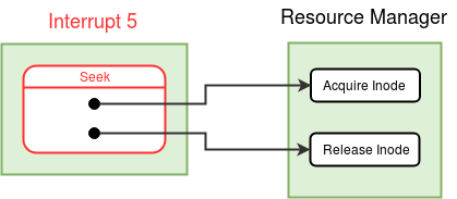
- Seek system call
Seek system call is used to move LSEEK pointer value for an open instance according to users requirement. Seek system call takes as argument a file descriptor and an offset from the user program. Seek updates the LSEEK field in the open file table corresponding to the open instance according to the provided offset value. Offset value can be any integer (positive, zero or negative). If the given offset value is 0, then LSEEK field is set to the starting of the file. For a non-zero value of offset, the given offset is added to the current LSEEK value. If the new LSEEK exceeds size of the file, then LSEEK is set to file size. If the new LSEEK position becomes negative, then Seek system call fails and return to user program with appropriate error code without changing the LSEEK position.
Implement Seek system call using detailed algorithm provided here.
Note :The implementation of Seek system call is
final.
Interrupt routine 15 (Shutdown system call)
Now that eXpOS supports writing to the files, the disk has to be consistent with the modified files before the system shuts down. Shutdown system call is modified in this stage to store back the buffers changed by the Write system call. Shutdown system call also terminates all the processes except current process, IDLE and INIT by invoking Kill All function of process manager module. Finally Shutdown halts the system after disk is made consistent.
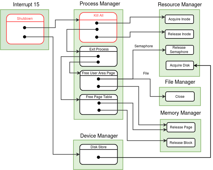
Modify Shutdown system call (interrupt routine 15) to perform the following addition steps.
- Invoke Kill All function of process manager module. Kill All terminates all the processes except IDLE, INIT and the process calling Shutdown.
- For every valid entry in the buffer table (BLOCK NUMBER is not equal to -1), if the DIRTY BIT field is set, then store back the buffer page of that buffer entry into the corresponding disk block by invoking Disk Store function of the device manager module.
Implement Shutdown system call using detailed algorithm provided here.
Kill All (function number = 5, process manager module)
Kill All function takes PID of a process as an argument. Kill All terminates all the processes except IDLE, INIT and the process with given PID. Kill All first locks all the files present in the inode table by invoking Acquire Inode function of resource manager module for every file. Locking all the inodes makes sure that, no process is in the middle of any file operation. If suppose a process (say A) is using a file and has locked the inode, then the process which has invoked Kill All will wait until process A completes the file operation and releases the inode. After acquiring all the inodes, Kill All terminates all the processes (except IDLE, INIT and process with given PID) by invoking Exit Process function of process manager module for every process. Finally, all the acquired inodes are released by invoking Release Inode function of resource manager module for each valid file.
Implement Kill All function using the detailed algorithm given in the process manager module link above.
Note :The implementation of the Shutdown
system call Kill All function is final.
Implementation of Shell executable file commands
Linux shell support file commands which makes working with files present in the system easier. An example of such file commands that Linux support is "ls". (Command "ls" lists all the files present in the current directory.) Now that all file related system calls are supported by eXpOS, we can implement few of these commands in eXpOS. This will enrich user experience for handling the files. Support for file commands ls, rm, cp, cat will be added to shell by implementing executable files for the commands. To implement the command ls, write a program ls.expl according to specification given in executable commands/files. Compile this program to generate executable file ls.xsm and load into the disk using XFS-interface. To run command "ls", run the executable file ls.xsm from the shell.
Implement commands ls, rm, cp, cat as executable files according to the specification of executable commands/files and load into the disk as executable files.
Making things work
Compile and load the modified files to the disk using XFS-interface.
Assignment 1: Write an ExpL program to take file name(string) and permission(integer) as input from the console and create a file with the provided name and permission. Write numbers from 1 to 1100 into the file and print the contents of the file in the reverse order (You will need Seek system call to do this). Run this program using shell.
Assignment 2: Write an ExpL program to append numbers from 2000 to 2513 to the file created in first assignment and print the contents of the file in reverse order. Run this program using shell.
Assignment 3: Run the program provided here using shell. The program takes a file name and permission as input and creates a new file with given input. It then forks to create two child processes. The two child processes act as writers and parent as reader. A file open instance is shared between two writers and there is separate open instance of the same file for reader. Two writers will write numbers from 1 to 100 into the file, with one writer adding even numbers and other writing odd numbers. The reader reads from the file and prints the data into the console concurrently. To synchronize the use of the shared open file between two writers a semaphore is used. The program prints integers from 1 to 100, not necessarily in sequential order.
Assignment 4: Run the program provided here using shell. The program first creates 4 files with values from s to 4*c+s, where s=1..4 and c=0..511. The program then, merges the 4 files taking 2 at a time, and finally, creates a merge.dat file containing numbers from 1 to 2048. Using cat.xsm, print the contents of merge.dat and check whether it contains the numbers from 1 to 2048 in ascending order.
-
POSTSCRIPT: How does an Operating System handle multiple devices in a uniform way?
eXpOS supported just one file system and just two devices - the disk and the terminal. The application interface to the file system and the terminal is the same - through the Read/Write system calls. The OS presents a single abstraction (or interface) to the application program for file read/write and console read/write, hiding the fact that these are two completely different hardware devices.
Let us review one of the system calls - say the Read system call. The system call code checks whether the read is issued for the terminal or the file system. If the read is from the terminal, then the system call redirects control to the terminal read function of the device manager. If the read is for a disk file, Read system call directly access the file system data structures to perform the system call (with appropriate calls to resource manager, and file manager for performing subtasks - See here).
Such a simple implementation works because eXpOS is dealing with just two devices. A modern OS might be connected to several hard disks and each hard disk may contain separate file systems on different disk partitions. Similarly, a plethora of devices - mouse, printer, USB devices and so on will be connected to the system. New devices may be needed to be connected to the system and the OS shouldn’t require re-design to accommodate each new device! How should then OS design be changed to handle such complexity?
The general principle of abstraction holds the key in designing the OS for handling a large number of devices and file systems. We first look at devices.
1. The OS will provide the same set of system calls to access every device - say, Open, Close, Read, Write, Seek, etc. (Some system calls may be vaccus for some devices - for instance, a Read operation on a printer or a Write to a mouse may perform nothing).
2. Open system call invoked with the appropriate device/file name returns a descriptor which shall be used for further Read/Write/Seek operations to the device.
3. The OS expects that the manufacturer of each device supplies a device specific interface software called the device driver. The device driver code for each device must be loaded as part of the OS. The OS expects that each device driver contains functions Open, Close, Read, Write and Seek. For instance, Write function in the print device driver may take as input a word and may contain low level code to issue appropriate command to the printer device to print the word.
4. When an application invokes a system call like Read, the system call handler checks the file descriptor and identifies the correct device. It then invokes the Read function of the appropriate device driver.
The principle involved in handling multiple file systems is similar. Each file system will be associated with a corresponding file system driver implementing Open, Close, Read, Write and Seek operations for the corresponding file system. Thus files and devices are handled in a single uniform manner.
The advantage of such abstract strategy is that any number of devices can be added to the system, provided device manufacturers and file system designers comply to provide appropriate device/file system drivers with the standard interface stipulated by the OS.
The following figure demonstrates the flow of control in device/file operations.
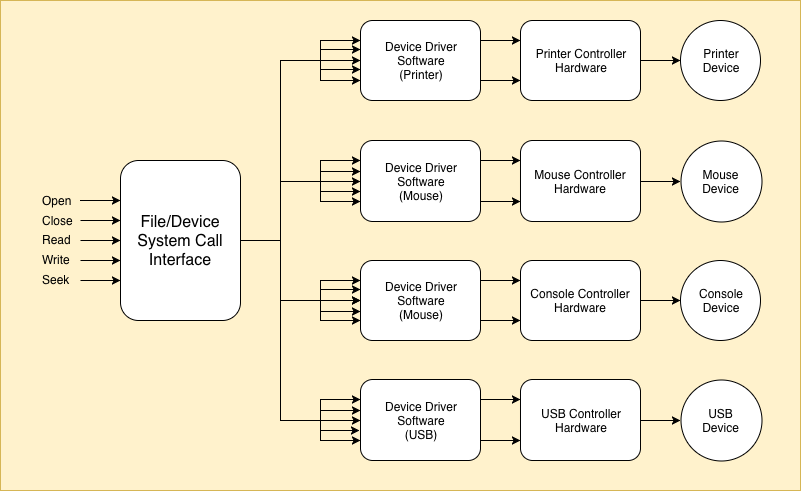
Note: Each device will have a programmable device controller hardware that is connected to the machine through a port/serial bus or some such interface. The device driver issues the Write/Read command to the device controller and the device controller in turn commands the device to perform appropriate action to get the task done. Thus, in the case of a printer, the device driver will issue commands to the printer controller, which in turn controls the printer actions.
Some additional implementation details and pointers to advanced reading concerning the above abstract principles are described below.
1. All modern file systems support a directory structure for file systems. (This is one major feature missing in eXpOS). In a directory file system, the filename field in the inode entry of a file will be a complete pathname describing the logical directory location of the file in the directory structure of the file system. The last part of the pathname will be the name of the file. For instance, a pathname “/usr/myfiles/hello” specifies a file with name “hello” in the directory “/usr/myfiles”.
2. Traditionally Operating systems have a default root file system that supports a directory structure. Other file systems are attached (mounted) as subdirectories of the root file system. When a Read/Write operation is performed on a file, the Read/Write system call checks the pathname of the file to determine which file system driver must be used for Read/Write operations. Devices are also mounted just like file systems.
Close
In this stage, we will enable eXpOS to handle multiple users by implementing multi-user system calls. Newusr and Remusr system calls are implemented to create new users and delete existing users in the system. The data structure called user table is maintained to store user name and encrypted password of each user in the system. The index of the user table entry for a user is the USERID for the user. Two special users called "kernel" (USERID = 0) and "root" (USERID = 1) are already initialized in the user table at the time of disk formatting (executing fdisk command in XFS-interface). Password of "kernel" is unspecified and "root" user is given default password "root" (The user table will store the encrypted form of the string "root"). System calls Setpwd, Getuname and Getuid are also implemented in this stage.
Login and Logout system calls are implemented to enable users to login into the system and logout from the system. From this stage onwards, we will modify the INIT process to work as a special login process, running with PID=1 and owned by the kernel (user id is set to 0). Login process enables users to login into the system with their user name and password. After a user logs into the system, the OS (the login system call) will schedule the shell process with PID=2. The shell will run in the context of the logged in user (that is, user id of the shell will be set to the user id of the logged in user). Note that the address space for the shell process would be already set up in the memory by the OS boot code. Hence the login process simply sets the shell process to ready state and invoke the scheduler to start its execution. The Shell program will be modified in this stage to support built-in shell commands.
Interrupt routine 17
The Login system call is implemented in the interrupt routine 17. Login has system call number 27. From ExpL programs, this system call is called using exposcall function.
- Login system call
Login system call takes two arguments 1) a user name (string) and 2) an unencrypted password (string). Login system call can only be invoked from the login process (PID = 1). The init process of eXpOS is called login process. Login process will ask the user to enter user name and password from the console and invokes Login system call with provided login credentials.
To login a user into the system, Login system call checks whether the user with given user name and password is present in the user table or not. Note that the password given as input is unencrypted and should be encrypted (using encrypt statement) before comparing to ENCRYPTED PASSWORD field in the user table. Login system call fails if the user with given user name and password is not found.
When a user with given login credentials is found, Login system call makes the shell process (PID = 2) ready for execution by changing the STATE field in the process table entry of shell process to CREATED. Although, login process does not explicitly invoke Fork and Exec system calls to create child, conceptually login process is considered as parent of shell process. So the PPID field in the process table entry of shell process is set to PID of login process (PID = 1). Also, login process must wait for shell process to terminate, so STATE of login process is changed to the tuple (WAIT_PROCESS, PID of shell). Then, Scheduler is invoked in order to schedule shell process for execution.
Note that the shell process is already loaded into the address space in boot module so Login system call is not required to load shell process into the memory.
Implement Login system call using detailed algorithm provided here.
Note :The implementation of Login system
call is final.
Interrupt routine 12
The Logout system call is implemented in the interrupt routine 12. Logout has system call number 28. From ExpL programs, this system call is called using exposcall function.
- Logout system call
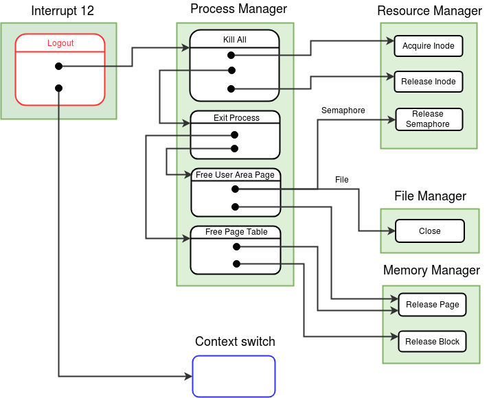
Logout system call is used to logout the current user from the system and does not take any arguments. Logout system call can only be executed from the shell process (PID = 2). Before leaving the system, all the non-terminated processes of the user should be terminated. As a consequence of terminating the processes, the resources acquired by these processes will be released. Logout system call invokes Kill All function of process manager module to terminate the processes. Recall that Kill All function terminates all processes in the system except idle, init (login) and the current process.
Logout system call changes the STATE of current process (shell) to TERMINATED. The starting IP of the shell process is stored at first word of user stack of shell, so that the next time when a new user is logged in and shell process is scheduled for the first time in the context of the new user, shell will run as newly created process. Login process (PID = 1) is made ready for execution and scheduler is invoked to schedule login process.
Implement Logout system call using detailed algorithm provided here.
Note :The implementation of Logout
system call is final.
Interrupt routine 16
The system calls Newusr, Remusr, Setpwd, Getuname and Getuid are implemented in the interrupt routine 16. Newusr, Remusr, Setpwd, Getuname and Getuid have system call numbers 22, 23, 24, 25, 26 respectively. From ExpL programs, these system calls are called using exposcall function.
- Newusr system call
- Remusr system call
- Setpwd system call
- Getuname and Getuid system calls
A user name and an unencrypted text password are arguments to the Newusr system call. Newusr system call can only be invoked from the shell process of the root user.
Newusr finds a free entry for the new user in the user table and initialize this entry with the provided user name and password. The password is encrypted (using encrypt statement) before storing it into the user table.
Implement Newusr system call using detailed algorithm provided here.
Remusr system call takes the user name of the user to be removed as an argument. Remusr system call can only be invoked from the shell process of the root user. A user can not be removed from the system if the user is the owner of one or more files in the system. To remove a user from the system, Remusr system call invalidates the entry in the user table corresponding to given username by storing -1 in the USERNAME and ENCRYPTED PASSWORD fields. Note that the special users "root" and "kernel" can not be removed using Remusr system call.
Implement Remusr system call using detailed algorithm provided here.
Setpwd changes the password of a user to newly provided password. It takes as arguments a user name and a new password from application program. Setpwd can only be executed by shell process. A user is permitted to change only its own password. The privileged user "root" has permission to change the password of any user. The "root" user is provided the default password "root". The password of root user can be changed later using Setpwd. Setpwd encrypts the provided password and replaces the ENCRYPTED PASSWORD field in the user table entry corresponding to provided user name.
Implement Setpwd system call using detailed algorithm provided here.
Getuname takes as argument a USERID from user program. Getuname returns the user name of the given USERID from the user table. Getuid takes a user name (string) as an argument from the user program. Getuid returns the USERID of the given user name. The system calls Getuname and Getuid can be executed from any process of any user.
Implement Getuid and Getuname system calls using detailed algorithms provided here.
Note :The implementation of Newusr, Remusr,
Setpwd, Getuname and Getuid system calls are final.
Modification to Shutdown system call
There is a slight modification in Shutdown system call. Shutdown system call can only be invoked from shell process. Until this stage, shell process was loaded as init program with PID = 1, but now login process is loaded as init and shell is loaded with PID = 2. So in Shutdown system call, modify the condition to check whether current process is shell or not, by comparing current PID to 2 (instead of the previous value 1).
Note :The implementation of Shutdown
system call is final.
Modifications to boot module and OS startup code
The boot module is modified to initialize the Shell process. Shell process has PID equal to 2. The process table entry and page table with index as 2 is initialized in the boot module for shell process. Heap, user stack and kernel stack pages are also allocated for the shell.
The boot module will set the shell process to TERMINATED state so that it will not be scheduled. The state of the shell process will be set to CREATED by the login system call when a valid user is logged in. This ensures that the shell process is scheduled only after a valid user is logged in.
Implementation Note:
Since Idle, Shell and Login processes are system processes that does pre-defined functionality, it is easy to design ExpL programs for them so that 1) they require no heap pages 2) Idle and login (init) processes require only one user stack page each 3) Idle and login code will fit into just one code page each (shell will be hard to implement without two pages of code). Hence, we will modify the boot code so as to allocate only one stack page apart from the user area page and code pages for Idle and Login processes. Shell process will be allocated two stack pages.
Note that the memory organization allocates two pages each for Idle and Login. Since the code for Idle and Login can fit into just one page, the second page can be allocated for their user stack. Kernel stack pages will have to be allocated in the free memory area. This leads to better memory utilization so that more concurrent processes may be run with the available memory. The page table entries for unallocated heap pages, stack page and code pages must be set to invalid.
- Changes for idle process allocation
- Load only the first code page from disk to memory (instead of two code pages). See disk/memory organization.
- Allocate second code page (70) as user stack page for idle (only one page for user stack is needed). Allocate memory page 76 for kernel stack of idle.
- Change the page table entries for stack and code pages according to above allocation. Also change the user area page number in the process table entry of idle.
- Store the starting IP address from the header of the first code page on the top of new user stack as the user stack page number is changed now for idle.
Steps to be done in the OS startup code to reflect the above changes are described below:
- Load shell process, int 16, int 12 (Logout), int 17 from disk to memory. See disk and memory organization here.
- Changes for init process allocation
- Load only the first code page from disk to memory (instead of two code pages). See disk/memory organization.
- Allocate second code page (66) as user stack page for init (only one page for user stack is needed). Allocate memory page 77 for kernel stack of init.
- Invalidate the heap page entries in the page table of the INIT process. Change the page table entries for stack and code pages according to above allocation. Also change the user area page number in the process table entry of init.
- Store the starting IP address from the header of the first code page on the top of new user stack as the user stack page number is changed now for init.
- Remove disk map table initialization for the init process as it is not needed any longer.
- Shell process allocation
- Load two code pages from disk to memory. See disk/memory organization.
- Allocate memory pages 78 and 79 for user stack of shell. Also allocate memory page 80 for kernel stack of shell.
- Set the library page entries to 63 and 64 in the page table of shell. Invalidate the heap page entries in the page table. Initialize the page table entries for stack and code pages according to above allocation. Also change the user area page number in the process table entry of shell.
- Initialize the process table entry of the shell process (PID = 2) as follows- Set the STATE field to TERMINATED. Store PID and PPID fields to 2 and 1 respectively. Store the kernel stack page number allocated above in the USER AREA PAGE NUMBER field. Set the KERNEL STACK POINTER field to 0 and USER STACK POINTER to 8*512. Also initialize PTBR and PTLR fields for the shell process.
- Initialize the disk map table entry of the shell process (PID = 2) as follows - Store the block numbers of the two code pages in the disk map table entry of the shell. Invalidate all other entries of the disk map table entry by storing -1.
- Store the starting IP address from the header of the first code page on the top of user stack for the shell process.
- Change the initialization of memory free list according to the memory pages allocated for idle, init and shell processes.
- Update the MEM_FREE_COUNT in the system status table to 47 as now 47 memory pages are available.
Steps to be done in the boot module to reflect the above changes are described below:
Note that shell process is set up for execution but STATE of the shell process is set to TERMINATED in the boot module. The shell process will be made READY only upon successful login of the user.
Login program
Login program is run as the Init process from this stage onwards. This program asks user for a user name and a password to log into the system. Login process uses Login system call to log in the user into the system. This is repeated in a loop. Write login program using the pseudocode provided here and load the XSM excutable as init program using XFS-interface.
Extended Shell program
Shell program is improvised to support the built-in shell commands and XSM executable commands/files according to the specification provided in eXpOS shell specification. An implementation of the ExpL shell program is given here. Compile and load this program as shell into the disk using XFS-interface. This program will be run as shell when a user logs into the system.
Now that multiple user related system calls are supported in eXpOS, the shell commands - "lu" and "ru" can be implemented. Implement commands lu, ru as executable files according to the specification of executable commands/files and load into the disk as executable files.
Making things work
Compile and load the newly written/modified files to the disk using XFS-interface.
-
Q1. Why Newusr, Remusr
and Setpwd system calls are permitted to execute only from shell program whereas
Getuid and Getuname can be executed from any application program?
The system calls Newusr, Remusr and Setpwd modify the data related to users in the user table. Getuid and Getuname system calls only access data related to users. As application programs other than Shell are not allowed to modify the user related data, system calls Newusr, Remusr, Setpwd are only executed from shell process.
Assignment 1: Test the system calls, login and shell process by performing following sequence of actions -
1) Login into the system as root user and change the password of root user using Setpwd command
2) Create new user using Newusr command
3) Log out from system
4) Login as newly created user
5) Create new files and perform file operations on them
5) List all users using "lu.xsm" executable file
6) Logout and again login as root user
7) Remove files owned by the new user using excutable file command "ru.xsm" from the shell of root.
You can further test the system by running all build-in shell commands and excutable files commands to make sure that implementation is correct.
Close
In this stage, we will learn how the limited physical memory pages of the XSM machine can be used effectively to run the maximum number of concurrent processes. To achieve this, we will implement the functions Swap Out and Swap In of Pager module (Module 6). Corresponding modifications are done in Timer Interrupt and Context Switch module as well.
eXpOS gives provision to execute 16 processes concurrently in the system and the number of memory pages available for user processes are 52 (from 76 to 127 - See memory organization). Consider a case, where every process uses four code, two heap, two user stack and one kernel stack pages. Then each process will need 9 memory pages. In this situation, the OS will run out of memory before all 16 processes can be brought into the memory, as the memory required will be 144 pages in total. A solution to this problem is following - when the OS falls short of free memory pages needed for a process, try to identify some inactive process whose memory pages could be swapped out to the disk. The memory pages freed this way can be allocated to the new process. At a later point of time, the OS can swap back the swapped out pages when the inactive process needs to be re-activated. This gives illusion of more memory than actual available memory. (Also see Virtual Memory.)
eXpOS uses an approach for memory management where the system does not wait for all the memory to become completely exhausted before initiating a process swap out. Instead, the OS regularly checks for the status of available memory. At any time if the OS finds that the available (free) memory drops below a critical level, a swap out is initiated. In such case, the OS identifies a relatively inactive process and swaps out some of the pages of the process to make more free memory available. The critical level in eXpOS is denoted by MEM_LOW (MEM_LOW is equal to 4 in present design). When available memory pages are less than MEM_LOW, eXpOS calls Swap Out function of pager module. Swap Out function selects a suitable process to swap out to the disk. The memory pages used by the selected process are moved into the disk blocks and the memory pages (except the memory pages of the library) are released. The code pages are not required to be copied to the disk as the disk already contains a copy of the code pages. The kernel stack page of a process is also not swapped out by eXpOS. However, the heap and the user stack pages are swapped out into the disk. eXpOS has 256 reserved blocks in the disk (256 to 511 - see disk organization) for swapping purpose. This area is called swap area.
A swapped out process is swapped back into memory, when one of the following events occur:
1) A process has remained in swapped out state for more than a threshold amount of time.
2) The available memory pages exceed
certain level denoted by MEM_HIGH
(MEM_HIGH is set to 12 in present design).
Each process has an associated TICK value (see process table) which is reset whenever the process is swapped out. The TICK value is incremented every time the system enters the timer interrupt routine. If the TICK value of a swapped out process exceeds the value MAX_TICK, the OS decides that the process must be swapped in. A second condition when the OS decides that a process can be swapped in is when the available number of free memory pages (see MEM_FREE_COUNT in system status table) exceeds the value MEM_HIGH.
When does the OS check for MEM_LOW/MEM_HIGH condition? This is done in the timer interrupt handler. Since the system enters the timer routine at regular intervals, this design ensures that regular monitoring of TICK/MEM_FREE_COUNT is achieved.
We will modify the timer interrupt handler in the following way. Whenever it is entered from the context of any process except a special swapper daemon process (to be described later), the handler will inspect the TICK status of the swapped out processes and the memory availability status in the system status table to decide whether a swap-in/swap-out must be initiated. If swap-in/swap-out is needed, the timer will set the PAGING_STATUS field in the system status table to SWAP_IN/SWAP_OUT appropriately to inform the scheduler about the need for a swap-in/swap-out. The timer handler then passes control to the scheduler. Note that the timer does not initiate any swap-in/swap-out now. We will describe the actions performed when the timer interrupt handler is entered from the context of the swapper daemon soon below.
We will modify the eXpOS scheduler to schedule the swapper daemon whenever PAGING_STATUS field in the system status table is set to SWAP_IN/SWAP_OUT. The OS reserves PID=15 for the swapper daemon process. (Thus the swapper daemon joins login, shell and idle processess as special processess initiated by the kernel.) The swapper daemon shares the code of the idle process, and is essentially a duplicate idle process running with a different PID. Its sole purpose is to set up a user context for swapping operations. A consequence of the introduction of the swapper daemon is that only 12 user applications can run concurrently now.
If the timer interrupt handler is entered from the context of the swapper daemon, then it will call the Swap-in/Swap-out functions of the pager module after inspecting the value of PAGING_STATUS in the system status table. Thus, swap-in/swap out will be initiated by the timer interrupt handler only from the context of the swapper daemon.
While swapping is ongoing, the swapper daemon may get blocked when swap-in/swap-out operation waits for a disk-memory transfer. The OS scheduler will run the Idle process in such case. Note that the Idle process will never get blocked, and can always be scheduled whenever no other process is ready to run.
Once a swap-in/swap-out is initiated from the timer, the OS scheduler will not schedule any process other than the swapper daemon or the idle process until the swap-in/swap-out is completed. This policy is taken to avoid unpredicatable conditions that can arise if other processes rapidly acquire/release memory and change the memory availability in the system while a swap operation is ongoing. This design, though not very efficient, is simple to implement and yet achieves the goal of having the full quota of 16 process in concurrent execution. (Note that the size of the process table in the eXpOS implementation outlined here limits the number of concurrent processes to 16).
The algorithms for Swap-in and Swap-out are implemented in the Pager Module (Module 6).
Modifications to Timer Interrupt

Timer interrupt handler is modified as follows:
The handler must check whether the current process is the swapper daemon. This condition can happen only when a swap operation is to be initiated. In this case, PAGING_STATUS field of the system status table must be checked and Swap_in/Swap_out function of the pager module must be invoked appropriately (SWAP_OUT = 1 and SWAP_IN = 2).
If the current process is the idle process, there are two possibilities. If swapping is ongoing (check PAGING_STATUS), one can infer that Idle was scheduled because the swapper daemon was blocked. In this case, the timer must invoke the scheduler. (The scheduler will run Idle again if the daemon is not unblocked. Otherwise, the daemon will be scheduled.) The second possibility is that swapping was not on-going. This case is not different from the condition to be checked when timer is entered from any process other than the paging process, and will be descibed next.
Generally, when the timer handler is entered from a process when scheduling was not on, the handler must decide whether normal scheduling shall continue or swap-in/swap-out must be inititiated. Swap-in must be initiated if the value of MEM_FREE COUNT in the system status table is below MEM_LOW. Swap-out must be inititated if either a) memory availability is high (MEM_FREE_COUNT value exceeds MEM_HIGH) or b) some swapped process has TICK value exceeding the threshold MAX_TICK.
Another modification in the Timer interrupt is to increment the TICK field in the process table of every NON-TERMINATED process. When a process is created by the Fork system call, the TICK value of the process is set to 0 in the process table. Each time the system enters the timer interrupt handler, the TICK value of the process is incremented. The TICK value of a process is reset to zero whenever the process is swapped out or swapped in. Thus the tick value of a process that is not swapped out indicates for how long that process had been in memory without being swapped out. Similarly, the tick value of a swapped out process indicates how long the process had been in swapped state. The swap-in/swap-out algorithms will use the value of TICK to determine the process which had been in swapped state (or not swapped state) for the longest time for swapping in (or out).
Modify Timer Interrupt implemented in earlier stages according to the detailed algorithm given here.
Pager Module (Module 6)
Pager module is responsible for selecting processes to swap-out/swap-in and also to conduct the swap-out/swap-in operations for effective memory management.
- Swap Out (function number = 1, Pager module )
- Swap In (function number = 2, Pager module )
- Get Swap Block (function number = 6, Memory Manager Module )
- Load module 6 (Pager Module) form disk to memory. See disk/memory organization.
- Initialize the SWAPPED_COUNT field to 0 and PAGING_STATUS field to 0 in the system status table to 0, as initially there are no swapped out processes.
- Initialize the TICK field to 0 for all the 16 process table entries.
- Update the MEM_FREE_COUNT to 45 in the system status table. (The 2 pages are allocated for the user/kernel stack for Swapper Daemon reducing the number from 47 to 45).
-
Q1. Why only READY state processes
are selected for swap in, even though swapped out processes can be in blocked state
also?
It is not very useful to swap in a process which is in blocked state into the memory. As the process is in blocked state, even after swapping in, the process will not execute until it is made READY. Until the process is made READY, it will just occupy memory pages which could be used for some other READY/RUNNING process.

Swap Out function is invoked from the timer interrupt handler and does not take any arguments. As mentioned earlier, the timer interrupt handler will invoke Swap Out only from the context of the Swapper Daemon.
Swap Out function first chooses a suitable process for swapping out into the disk. The processes which are not running and are in WAIT_PROCESS or WAIT_SEMAPHORE state are considered first for swapping out (why?). When no such process is found, the process which has stayed longest in the memory is selected for swapping out into the disk. To detect the processes which has stayed longest in the memory, the TICK field in the process table is used. Thus the process with the highest TICK is selected for swapping out.
Now that, a process is selected to swap out, the TICK field for the selected process is initialized to 0. (From now on, the TICK field must count for what amount of time the process has been in memory). The code pages for the swapping-out process are released and the page table entries of the code pages are invalidated. The process selected for swapping out, can have shared heap pages. To simplify implementation, shared heap pages are not swapped out into the disk. Again, to simplify implementation, the kernel stack page is also not swapped out. Non-shared heap pages and user stack pages are stored in the swap area in the disk. Get Swap Block function of the memory manager module is invoked to find free blocks in the swap area. These memory pages are stored into the allocated disk blocks by invoking Disk Store function of the device manager module and disk map table is updated with the disk numbers of corresponding pages. Memory pages of the process are released using Release Page function of memory manager module and page table entries for these swapped out pages are invalidated. Also the SWAP FLAG in the process table of the swapped out process is set to 1, indicating that the process is swapped out.
Finally, the PAGING_STATUS in the System Status Table is reset to 0. This step informs the scheduler that the swap operation is complete and normal scheduling can be resumed.
Implement Swap Out function using the detailed algorithm given in the pager module link above.

Swap In function is invoked from the timer interrupt handler and does not take any arguments.
The Swap In function selects a swapped out process to be brought back to memory. The process which has stayed for longest time in the disk and is ready to run is selected. That is, the process with the highest TICK among the swapped-out READY processes is selected).
Now that, a process is selected to be swapped back into the memory, the TICK field for the selected process is initialized to 0. Code pages of the process are not loaded into the memory, as these pages can be loaded later when exception occurs during execution of the process. Free memory pages for the heap and user stack are allocated using the Get Free Page function of the memory manager module and disk blocks of the process are loaded into these memory pages using the Disk Load function of the device manager module. The Page table is updated for the new heap and user stack pages. The swap disk blocks used by these pages are released using Release Block function of the memory manager module and Disk map table is invalidated for these pages. Also the SWAP FLAG in the process table of the swapped in process is set to 0, indicating that the process is no longer swapped out.
Finally, the PAGING_STATUS in the System Status Table is reset to 0. This step informs the scheduler that the swap operation is complete and normal scheduling can be resumed.
Implement Swap In function using the detailed algorithm given in the pager module link above.
Note :[Implementation Hazard] There is a
possibility that the code of the Pager module will exceed more than 2 disk blocks (more than
512 instructions). Try to write optimized code to fit the pager module code in 2 blocks. You
can use the following strategy to reduce the number of instructions. According to given
algorithm for Swap Out function, the actions done for code pages, heap pages, user stack pages are written separately. This results in calling Release Page function 2
times, Get Swap Block and Disk Store functions 2 times each. Combine these actions into a
single while loop where each module function is called only once. The loop should traverse
through the page table entries one by one (except library page entries) and perform
appropriate actions if the page table entry for a page is valid. Apply similar strategy for
Swap In function also.
Get Swap Block function does not take any arguments. The function returns a free block from the swap area (disk blocks 256 to 511 - see disk organization) of the eXpOS. Get Swap Block searches for a free block from DISK_SWAP_AREA (starting of disk swap area) to DISK_SIZE-1 (ending of the eXpOS disk). If a free block is found, the block number is returned. If no free block in swap area is found, -1 is returned to the caller.
Implement Get Swap Block function using the detailed algorithm given in the memory manager module link above.
Note :The implementation of module functions Swap Out, Swap In and Get Swap Block are final.
Modification to Context Switch Module (Module 5)
Previously, the Context Switch module (scheduler module) would select a new process to schedule according to the Round Robin scheduling algorithm. The procedure for selecting a process to execute is slightly modified in this stage. If swap-in/swap-out is ongoing (that is, if the PAGING_STATUS field of the system status table is set), the context switch module schedules the Swapper Daemon (PID = 15) whenever it is not blocked. If the swapper daemon is blocked (for some disk operation), then the idle process (PID = 0) must be scheduled. (The OS design disallows scheduling any process except Idle and Swapper daemon when swapping is on-going.) If the PAGING_STATUS is set to 0, swapping is not on-going and hence the next READY/CREATED process which is not swapped out is scheduled in normal Round Robin order. Finally, if no process is in READY or CREATED state, then the idle process is scheduled.
Modify Context Switch module implemented in earlier stages according to the detailed algorithm given here.
Modifications to OS Startup Code
Modify OS Startup Code to initialize the process table and page table for the Swapper Daemon (similar to the Idle Process).
The final algorithm is given here.
Modifications to boot module
Modify Boot module to add the following steps :
Assignment 1: Write an ExpL program which invokes Fork system call four times back to back. Then, the program shall use Exec system call to execute pid.xsm file (used in stage 21) to print the PID of the processes. Invoking four Forks back to back is supposed to create 16 new processes, but only 12 new processes will be created as eXpOS will run out of process table entries. Run this program using the shell in the context of a user.
Assignment 2: Run the program provided here using shell in the context of a user. The program given in the given link will first read a delay parameter and then, call the Fork system call and create 12 processes. Each process prints numbers from PID*100 to PID*100 + 7. After printing each number, a delay function is called with the the delay parameter provided.
Assignment 3: Run the program provided here using shell in the context of a user. The program will create a file with name as "num.dat" and permission as open access. Integers 1 to 1200 are written to this file and file is closed. The program will then invoke Fork system call four times, back to back to create 12 processes and Exec system call is invoked with file "pgm1.xsm". The program for "pgm1.xsm" is provided here. "pgm1.xsm" will create a new file according to the PID of the process and read 100 numbers from file "num.dat" from offset (PID-3)*100 to (PID-3)*100+99 and write to newly created file. After successful execution, there should be 12 data files each containing 100 consecutive numbers (PID-3)*100+1 to (PID-3)*100+100.
Assignment 4: Run the program provided here using shell in the context of a user. The program will create a file with name as "numbers.dat" and permission as open access and open the file. The program also invokes Semget for a shared semaphore. The program will then invoke Fork system call four times, back to back to create 12 processes. The 12 processes now share a file open instance and a semaphore. Each process will write 100 numbers consecutively (PID*1000+1 to PID*1000+100) to the file "numbers.dat". Each process then invokes the Exec system call to run the program "pgm2.xsm". The program for "pgm2.xsm" is provided here. "pgm2.xsm" will create a new file according to the PID of the process and read 100 numbers from file "numbers.dat" from offset (PID-3)*100 to (PID-3)*100+99 and write to newly created file. After successful execution, there should be 12 data files each containing 100 numbers from X*1000 to X*1000+99, where X ∈ {3,4..15}. The numbers written by a process in the newly created file need not be the same numbers the process has written in "numbers.dat" file.
Assignment 5: Run the program (merge.expl) provided here using shell in the context of a user. The merge.expl program, first stores numbers from 1 to 512 in a random order into a file merge.dat. It then forks and executes m_store.expl which creates 8 files temp{i}.dat, where i=1..8 and stores 64 numbers each from merge.expl. Then, all the temporary files are sorted by executing m_sort.expl. Next, the first ExpL program forks and executes m_merge.expl which merges all the temporary files back into merge.dat and finally, prints the contents of the file in ascending order. If all the system calls in your OS implementation works correctly, then numbers 1 to 512 will be printed out in order.
Note :To run the program provided by the user, Shell process first invokes fork
to create a child process. Shell will wait until this first child process completes its
execution. When the first child exits, shell will resume execution even if some processes
created by the given program are running in the background. This can lead to the following
interesting situation. Suppose that all active processes execept idle, login and shell were
swapped out and the XSM simulator is waiting for terminal input from the user
into the shell. In this case, you will have to issue some command to the
shell, so that the system keeps on running.
Close
Installation
Since you will be working on a new machine architecture on this stage, upgraded versions of the XSM machine simulator, SPL compiler, ExpL compiler and xfs-interface has to be downloaded. Create a new folder and download the upgraded eXpOS package so that there are no conflicts with the old version. The OS kernel code and other programs will have to be copied into the new folder before you start working.
Follow the installation instructions here to download the upgraded eXpOS package.
Outline
In this stage, you will port eXpOS to a two core extension of XSM called NEXSM. The specification of the OS does not undergo any change from the point of view of the end user or the application programmer (that is, the API - high level library interface or ABI - low level system call interface are unchanged except for some insignificant updates). Thus, the upward (application) interface of the OS does not change.
What changes is the downward (architecture) interface. NEXSM supports a few more memory pages, a few more disk blocks and more significantly, a second core processor. The question is - how to make the best use of the available parallelism with minimal changes to the eXpOS code?
The bootstrap process happens on one of the cores (called the primary core in NEXSM specification). The bootstrap code completes the initial set up operations and then start the other core (called secondary core) into parallel action. A read only register called CORE will have value 0 in the primary and 1 in the secondary. This allows the kernel code to determine the core on which it is executing.
It is absolutely necessary to have a careful reading of the NEXSM architecture specification before proceeding further.
Once the OS is up and running on the two-core machine after bootstrap, each core runs the same OS code and schedules processes parallelly. The fundamental issue to be addressed is to ensure that parallel actions of OS on the two cores do not lead the OS into an inconsistent state.
Handling concurrency is a tricky issue. Here, we impose a few conservative design level restrictions to the level of parallelism permitted so that a simple and comprehensible design is possible. The resultant design is not an efficient one; but it is sufficient to demonstrate the underlying principles. The constraints imposed are the following:
- A single process will never be scheduled simultaneously on both the cores. The scheduler will be designed so as to ensure this policy. Only one core will run scheduling code at a given time. This makes implementation of the first policy straight-forward.
- Only one core will be executing critical kernel code at a time. By critical kernel code, we mean 'kernel code that updates the Disk data structures and System-Wide data structures'. We will ensure that critical kernel code gets executed quickly and thus a core will never have to wait for a long time for the other core to leave critical section. (Non-interfering routines of the OS kernel are allowed to run parallelly - for instance both cores can enter the timer interrupt routine parallely; one core may be running the scheduler while the other is executing a system call and so on.)
-
A few other simplifying design decisions are:
- The Login process and Shell Process will be run only from the primary. (As a consequence, logout and shutdown will be initiated only from the primary). The pager module will also be run only from the primary.
- An additional IDLE process is created at boot time (called IDLE2 with PID=14). IDLE2 will be scheduled in the second core when no other process can be scheduled. (The primary will schedule IDLE when no other process can be scheduled as in the current design). IDLE2 will never be swapped out. The primary core will never schedule IDLE2 and the secondary core will never schedule IDLE.
- When either logout or paging is initiated from the primary, the scheduler running on the secondary core will schedule the IDLE2 process.
How can the kernel implement the policies (a) and (b)? The implementation mechanism is to maintain two access lock variables - called SCHED_LOCK and KERN_LOCK. The kernel maintains an access lock table (starting at location 29576 - see here) where these lock variables are stored. The use of these variables will be described in detail below.
Upon entry into a system call (respectively, scheduler code), the kernel first checks whether the other core is executing a system call code (respectively, scheduler code). If that is the case, the kernel waits for the other core to finish the critical system call code (respectively, scheduler code) before proceeding.
Data Structure Updates
The system status table will now contain two new entries.
- CURRENT_PID2: Stores the PID of the process running on the secondary core.
- LOGOUT_STATUS: This field is set to 1 if logout is initiated on the primary core; set to 0 otherwise. If LOGOUT_STATUS is on, only IDLE2 will be scheduled in the secondary core.
A new data structure called access lock table is introduced. The fields that are of interest in this data structure are the following:
a) KERN_LOCK b) SCHED_LOCK
- When the kernel enters a system call/exception handler (in either core), it first checks whether KERN_LOCK=1 (If so, the value should have been set to 1 by the kernel code running on the other core). In that case, the kernel executes a spin lock (details will follow) till the kernel code running on the other core sets the lock back to zero. When the lock becomes available, the system call/exception handler sets KERN_LOCK to 1 and proceed with the normal execution of the system call. This ensures, mutual exclusion (between the two cores) for the critical code of system calls/exception handler. Since paging code is critical, KERN_LOCK is set before invoking the pager module (from the timer interrupt handler) and set back to zero upon return from the pager module.
- At any point of time, if the system call/exception handler has to block for some event, it sets KERN_LOCK=0 before invoking the scheduler so that if the other core is waiting for KERN_LOCK, it can acquire the lock and enter critical section. Upon getting scheduled again, the system call/exception handler must do a spin lock again and set KERN_LOCK to 1 before proceeding. This protocol ensures that a core holds onto the kernel lock only for short durations of time. This also ensures that the kernel running on one core never holds on to SCHEDULE_LOCK and KERN_LOCK simultaneously. Finally, KERN_LOCK is set to zero before return to user mode after completion of the system call handler/exception handler code.
- Before starting scheduling actions, the scheduler code first checks whether SCHED_LOCK is set to 1 by the scheduler code running on the other core. If the lock is set, a spin lock is executed (details will follow) till the scheduler code running on the other core resets the lock back to zero. This ensures that when scheduling actions are ongoing in one core, the other core waits. Note that scheduler code is small and will execute quickly, and hence the wait will not be for long. SCHED_LOCK is set to 0 at the end of scheduling.
-
The fundamental point that must be understood is that the test and set operations on KERN_LOCK and SCHED_LOCK need to be atomic, for otherwise while one core is testing the value of a lock, the other core can change it from 0 to 1 and both the cores will simultaneously enter critical section. Atomicity of test and set operations can be achieved in two ways:
- Hardware solution: If the hardware provides instructions to perform atomic test and set operations on a variable then the facility can be used.
- Software Solution: Even if no hardware support is available, there are clever software solutions that achieve synchronization. Peterson’s algorithm is one famous solution.
Access Control Module
You will add a new module that implements atomic test and set operations on KERN_LOCK and SCHED_LOCK. The module will be added as Module 8 (memory pages 132-133). Access control module supports the following functions:
- AcquireKernLock()
- AcquireSchedLock()
- ReleaseLock(LockVarAddress)
Note: The eXpOS design documentation supports a general purpose lock called GLOCK, reserved for future enhancements. The present implementation does not need it and we will not discuss it in the roadmap.
The AccessLock functions can be implemented using the NEXSM TSL instruction to ensure that locking is atomic. SPL provides the tsl instruction which is translated to the XSM TSL machine instruction. The general locking logic in SPL would be the following.
Acquire****Lock() {
    ....
    ....
    while (tsl (LockVariableAddress) == 1)
       continue;
    endwhile;
}
This would translate to the following XSM code (or equivalent):
L1: TSL Ri, [LockVariableAddress]
MOV Rj, 1
EQ Ri, Rj
JNZ Ri, L1
The code atomically reads the lock variable repeatedly until its value is zero. Once the value is founf to be zero, the value is set to one. This procedure is sometimes called a spin lock. A spin-lock is advisable only when the CPU only make a few iterations before the resource could be accessed, as in the present case.
Important: LOGOUT_STATUS will be used by the Acquire Kernel Lock function of the Access Control Module in the following way. When the Acquire Kernel Lock function is called from the secondary core, if PAGING_STATUS or LOGOUT_STATUS is on, then the lock must not be acquired. Instead, the state of the current process must be set to READY and the scheduler must be invoked. This is because when paging module is running or if the system has initiated logout (from the primary), normal processing is stopped and only IDLE2 must be scheduled in the secondary. (The scheduler will be designed so that under these circumstances, only IDLE2 will be scheduled for execution).
The access control module algorithms are given here.
Bootstrap Procedure
When NEXSM boots up, only the primary core will execute. Upon execution of the START instruction from the primary (see NEXSM specification), the secondary starts execution from physical address 65536 (page 128 - see Memory Organisation). Hence, the primary bootstrap routine (OS startup code) must load the secondary bootstrap loader into memory before issuing START instruction. The IDLE2 process needs to be set up in memory. The access lock table entries are also initialized during bootstrap. A couple of new entries will be added to the system status table as well.
The required changes to the primary OS Startup code/boot module are summarized below:
- Transfer the secondary bootstrap loader code from disk to memory (from disk block 512 to memory page 128). The access control module also must be loaded from disk to memory (blocks 516-517 to pages 132-133) - see disk and memory organization. (Note: The design allows 2 blocks of secondary bootstrap code, but you will only need one block for the present eXpOS version).
- Set up the page tables for IDLE2 (PID=14) in memory. Since one user stack and one kernel stack pages will have to be allocated for IDLE2 (the first two free pages, 83 and 84 may be allocated). The memory free list has to be updated accordingly. Also, the free memory count in the system status table will need corresponding update. The process table entries for IDLE2 will be set (similar to IDLE). In particular, the state has to be set to RUNNING (as it is going to be running very soon on the secondary core!).
- New entries in the system status table must be initialized. a) CURRENT_PID2 must be set to the the PID of IDLE2 process (PID=14). b) LOGOUT_STATUS must be set to 0.
- The access control variables KERN_LOCK and SCHED_LOCK of the Access Lock Table must be initialized to 0.
- Issue the START instruction to start the secondary core into execution.
The secondary bootstrap code that begins parallel execution upon START must do the following:
- Set up the return address in user stack of the IDLE2 process; SP, PTBR and PTLR registers must be updated.
- Execute ireturn to run IDLE2.
Thus, the primary and secondary bootstrap code will schedule IDLE (PID=0) and IDLE2 (PID=14) on the respective cores at the end of system startup.
Modifications to Scheduler Module
The scheduler module requires the following modifications:
- At the beginning of execution, determine whether scheduler is running on the primary or the secondary (read the CORE register value).
- SCHED_LOCK must be acquired by calling AcquireSchedLock() function of the access control module.
-
If the core is primary, there is no change to existing algorithm except that:
- IDLE2 (PID=14) must not be scheduled. (IDLE2 is scheduled only in the secondary).
- The Process which is currently running on the secondary core must not be scheduled (This can be determined by reading CURRENT_PID2 field of the system status table).
- If LOGOUT_STATUS=1 and the secondary core is not running IDLE2, then schedule IDLE (wait for the current running process to be scheduled out of the secondary core).
-
If the core is secondary, there is no change to existing algorithm except that:
- If PAGING_STATUS or LOGOUT_STATUS is set (in the system status table), then IDLE2 must be scheduled).
- IDLE (PID=0), LOGIN (PID=1), SHELL (PID=2) and SWAPPER_DAEMON (PID=15) should never be scheduled, as the eXpOS design stipulates that these processes will run only on the primary.
- Process which is currently running on the primary core must not be scheduled (read CURRENT_PID field of the system status table).
- The PID of the process that is selected for scheduling in the secondary core must be set to CURRENT_PID2 field of the system status table.
- SCHED_LOCK must be released by calling ReleaseLock() function of the access control module before return from the scheduler. (Note: If the new process to be scheduled is in CREATED state, the scheduler directly returns to user mode using the ireturn statement. Do not forget to release SCHED_LOCK in this case as well!).
Modifications to Exception Handler and System Calls
- Before starting any system call, KERN_LOCK must be acquired by invoking AcquireKernLock() function of the access control module.
- The value of Current PID will be different on the primary and the secondary cores - [SYSTEM_STATUS_TABLE + 1] in the primary core and [SYSTEM_STATUS_TABLE + 6] in the secondary core. (Implementation trick: the formula [SYSTEM_STATUS_TABLE + 5*CORE + 1] works on both the cores!!).
- ReleaseLock() function of the access control module must be used to release KERN_LOCK before, a) any call to the scheduler, b) return from the system call/exception handler to the user program. Note that, the scheduler can be invoked not only from system calls, but also from kernel modules. In all such cases, KERN_LOCK must be released before invoking the scheduler.
- AcquireKernLock() of the access control module must be invoked at any point after return from the scheduler (inside system calls as well as kernel modules).
Important Note: When a process has acquired KERN_LOCK, any other process trying to acquire KERN_LOCK on the other core will be in a spin lock, doing no userful processing. Hence, your implementation should ensure that ReleaseLock() is invoked at the earliest point when it is safe to allow parallel execution of critical code from the other core. Further note that under normal conditions (except in Logout, Shutdown, etc.), updates to process table and page table entries of a process are private to the process and there is no harm in letting other processes to run parallelly when a system call needs to make updates only to these data structures.
Modifications to Timer Interrupt Handler
- Do not invoke pager module from the secondary core.
- When running on the primary core, call AcquireKernLock() and ReleaseLock(KERN_LOCK) of the access control module before and after calling pager module.
Modifications to Process Manager and Pager Modules
- Kill All function in process manager module must not call Exit Process function for IDLE2 (PID=14) as this process is never killed.
- Pager module must not swap out IDLE2 (PID=14).
Modifications to Logout System Call
- In Logout System call, first set LOGOUT_STATUS=1 in the system status table, but then call the scheduler (wait until secondary core schedules IDLE2 before proceeding).
- After execution of Kill All function, set LOGOUT_STATUS=0. In the system status table.
Note: Since, Logout is also a system call, all the updates done to system calls in general will apply to Logout as well.
Modifications to Shutdown System Call
In Shutdown system call, before calling Kill All function of the process manager module, reset the secondary core (using RESET instruction of NEXSM) and set SCHED_LOCK to 0.
Note: Since, Shutdown is also a system call, all the updates done to system calls in general will apply to Shutdown as well.
We have tried to include all the necessary details. We leave it to you to figure out anything that is missing here and get the OS working!!
-
Q1. Suppose the scheduler is about to resume execution of a process which was blocked while executing some system call, what would go wrong if we modify the present design so that scheduler simply sets KERN_LOCK=1 before scheduling it (instead of the process doing a AcquireKernLock() inside the system call after being scheduled)? Note that the scheduler will not run simultaneously on both the cores.
If the scheduler simply sets KERN_LOCK=1, then there is a possibility that the other core may have already acquired the KERN_LOCK. This causes both the cores to execute the critical section code parallelly, which will corrupt the OS data structures. Also, AcquireKernLock() function must be called from the system call, instead of the scheduler, as the return from scheduler may be to the timer interrupt handler which doesn't require a Kernel Lock.
-
Q2. Why should the logout system call wait for the secondary to execute IDLE2 before proceeding?
The Logout system call terminates all the processes from 4 through 13 by calling the Kill All function in the process manager module. So, if this system call terminates the currently running process in the secondary core, the memory pages assigned to the process will be released by freeing the page table and user area page, which causes the secondary core to raise an exception. Waiting for the secondary core to schedule IDLE2 prevents this from happening.
Assignment 1: Run all the test cases of the previous stage.
Assignment 2: Modify the access locking algorithm to use Peterson’s algorithm instead of using the TSL instruction and run all test cases.
Thought Experiment: Right now, all kernel code (except scheduler) operates with a single KERN_LOCK. Instead, suppose you put different lock variables for each kernel data structure, clearly, better use of parallelism can be achieved. What are the issues you have to consider when such a re-design is one? (You don’t have to do the experiment, but try to work out the design details on pen and paper). Do you think this will make the kernel run considerably faster? Can such a design lead to deadlocks?
Close