XSM Unprivileged Mode Execution
In this tutorial we will explain the unprivileged mode execution of XSM machine.
Please go through Paging specification and Virtual address space model before reading further.
In the privileged mode, a memory address refers to the actual physical memory address. For instance, the instruction sequence:
MOV SP, 1000
PUSH R0
The first instruction sets stack pointer register SP to 1000. The PUSH instruction will first increment SP (to value 1001) and then transfers contents of the register R0 to the top of the stack - that is - to the memory location 1001 pointed to by SP.
However, PUSH and other unprivileged instructions have a different behaviour when executed in unprivileged mode. PUSH will increment SP to 1001 as before, but the memory address to which contents of R0 is copied is determined in a different way. The machine will treat the contents of SP as a logical address, find out the physical address corresponding to the logical address 1001 using the address translation mechanism of XSM and transfer contents of R0 to that location. We discribe the address translation process below.
Address Translation
The translation of a logical address to physical address is done completely by the machine's paging hardware. The sequence of steps involved may abstractly be described by the following steps, which will be described in detail with examples soon:
Given a logical address – find the logical page number and offset specified by the address.
Search the page table to find the physical page number from the logical page number.
Multiply physical page number by page size to find the physical page address.
physical address = physical page address + offset.
The machine assumes that the PTBR register holds the base(starting) address of the page table in memory. Since PTBR register can be accessed only in privileged mode, your code must have set the PTBR register to store the address of the page table before entering unprivileged mode execution. Moreover, to get the address translation hardware to work the way you want it to, your must write privilaged code to set appropriate values in the page table before executing an IRET instruction to switch the machine to unprivileged mode . Thus, some setup work needs to be done in the privileged mode before a switch to unprivileged mode.
How does the machine translate a logical address – say 1001- to the corresponding physical address? The machine does the following sequence of actions. Let us assume that PTBR contains value – say 3000, set previously.
Calculate,
logical_page_number = logical_address DIV page_size
= (1001 DIV 512) = 1.Calculate,
offset = logical_address MOD page_size
= (1001 MOD 512)
= 489.Find,
the page_table_address = contents of PTBR = 3000.Find,
physical_page_number = value stored in address (page_table_address + 2 x logical_page_number)
= value stored in address (3000 + 2 x 1)
= value stored in address 3002.
Suppose that this value is 7. (The minimum value possible is 0 and the maximum value possible is 127 – why?).Calculate,
physical_address = physical_page_number x page_size + offset
= 7 x 512 + 489 = 4073.
Thus, the instruction PUSH R0 in the code shown in the beginning will transfer contents of R0 to the physical address 4073.
There are several points to mention here. The PUSH operation will be successful only if the auxiliary information for logical page number 1 in the page table is set to ensure that the page is valid. Otherwise, the machine will generate an exception, switching back to privileged mode. We will discuss exception handling later.
To get a better picture of the unprivileged mode execution, we need to digress briefly to discuss the underlying theoretical concepts.
Paging and virtual memory
First of all, as an OS designer, why should you learn to run the machine in unprivileged mode at all?
An OS will have to allow concurrent execution of other "user programs" (or application programs). The OS needs to be careful not to allow one application program to run malicious code that corrupts other user programs or the OS itself. This requires provision to run application programs in a "less privileged" mode of execution where only a limited set of instructions can be executed, and only limited memory space and system resources are accessible. Architecture support is needed to achieve this. The architecture support provided by the XSM machine is the support for the XSM virtual machine model.
When a program runs in unprivileged mode on the XSM machine, only a restricted machine model is available to the application program. A key architectural technique that supports such a model is paging. Paging allows the OS to provide each application program running in unprivileged mode with a virtual (or logical) address space. The application's access can be restricted to this address space.
The virtual address space (or the logical address space) of an application is a contiguous memory address space starting from logical address 0 to a maximum limit set by the OS. Thus the addresses found in the application program's code shall only be between 0 and the maximum limit. Each application's code and data must fit into its logical address space. The OS views this address space as being divided into logical pages of 512 words each. Hence logical addresses 0 to 511 belongs to logical page 0 of the program, logical addresses 512 to 1023 belongs to logical page 1 and so forth.
The XSM machine on the other hand has 128 physical pages into which the logical pages of all programs running in the system has to be mapped into. Hence, there needs to be some data structure to map the logical pages of each program to the corresponding physical pages. This data structure is called the page table. The OS maintains a seperate page table for each program that stores the physical page number to which each logical page of the program is mapped to. Note that the page table is a "meta data" about a program maintained by the OS. The OS stores the table outside the address space of the process and the process has no access to it.
When a program is executed in unpreviliged mode, the logical address must be translated on the fly to the corresponding physical addresses. This requires support from the hardware. XSM paging hardware mechanism provides the requred support. The XSM machine expects that the OS sets up the page table for each program in the memory, adhering to a certain format and set the PTBR/PTLR registers properly before running a program is unpreviliged mode. Next we describe in detail how this must be done.
Setting up Paging for an Application
Before running an application program in unpreviliged mode, the OS must set up the application's page table data and values of PTLR and PTBR. Note that this set up code must run in previliged mode (why?).
The steps are as given below
Set the PTLR register to define the address space maximum limit.
Set up a valid page table in memory and the PTBR register to the beginning address of the page table of the particular application.
Set up the application's stack. Set SP to point to the top of the stack.
Compute the physical address corresponding to the logical address in SP. Then, copy the logical address of the first instruction (entry point) that much be fetched after IRET into this physical memory location and execute IRET.
We explain each of the above four steps in detail:
Step 1: XSM stipulates that the address space limit of an application must be a multiple of XSM page size=512.
Suppose, the OS decides that the application must be provided with a virtual address space of 10 pages,
then the PTLR register must be set to value 10. In this case, the logical address space of the application
will be between 0 and 512x10-1=5119. (The ExpOS kernel that you design sets the address space of every
application to 10 pages).
While executing in user mode, if an instruction in the application refers to a logical address beyond this limit, the machine will raise an exception. This will result in the machine switching to privileged mode and control transferred to the starting address of the exception handler routine (memory address 1024 – see Machine Organisation).
For example, if PTLR=10 and if the application contains an instruction like MOV R0, [6000],
an exception will be generated because the instructions contain addresses outside the logical address space
set by PTLR. As another example, JMP 7000 instruction will result in setting IP to 7000 and in the very next
fetch cycle, an exception will be generated because an instruction fetch will be attempted from a logical address
beyond the address space. If SP holds value 5119, then a PUSH instruction will similarly result in an exception. Exception handling will be discussed in detail later.
Step 2: Once the address space size is determined by PTLR value, a page table has to be set up in the memory
for the application to tell the hardware which logical page is mapped to which physical page. The number of entries in the page
table is determined by the number of pages allocated to the application. Thus if PTLR=10, then the page table
must contain ten entries.
Each page table entry requires two memory words and contains information about the corresponding logical page. That is, the first two words of the page table contain information about logical page 0, the next two about logical page 1 and so on. If PTLR=10, the page table of the application will require total 20 memory words.
The first word of each page table entry contains the physical page number of the corresponding logical page. The second word stores auxiliary information. The auxiliary information for a page consists of four binary values:
a) Reference bit,
b) Valid bit,
c) Write permission bit,
d) Dirty bit.
Proper values for Valid (V bit) and the Write permission bit (W bit) must be set by your privileged code of step 2 before starting unprivileged mode execution. We describe these settings below.
If the Valid bit is set to 0, the page table entry is considered invalid. In this case, if any logical address accessing the page will generate an exception. If the write permission bit is set to 0, the application will not have write permission to the page.
For example, if entry 0 of the page table has valid bit 0, then an instruction like MOV [100], R0 or JMP 112 will generate an exception. If entry 0 of the page table has write permission bit 0, then MOV [100], R0 that modifies the page will raise an exception. However, if the valid bit is 1, MOV R0,[100] or JMP 112 that do not modify the contents of the page will execute normally in unprivileged mode if the write bit is 0.
The Reference bit and the Dirty bit are set by the machine. When the application is executing, if an address is generated accessing some logical page, then the reference bit of the page is set automatically to 1 by the machine. For instance, MOV R0, [1500] accesses the logical page 2 and hence the reference bit of the corresponding page table entry will be set to 1 by the machine automatically. The dirty bit is set if the instruction modifies the contents of the page. MOV R0, [1500] does not result in the machine setting the dirty bit for logical page 2 because the instruction does not modify contents of the page. However MOV [1500], R0 sets the dirty bit.
Before we move into the next step of setting up the application's stack, we need to figure out what initial setting the application expects from the OS. Basically, there must be some pre-defined convention regarding the initialization of the application's stack between the application and the OS. Similarly the OS should know which is the first instruction that must be executed when the application is run in unpreviliged mode in order to transfer control to that instruction. We digress briefly to discuss these finer details.
Loading application to address space
Suppose an application contains 3 pages of code. Assume that the first page of the code has been loaded into physical page number 100 and second page to 110. Assume that the third page is not loaded into memory. (The load instruction can be used in the privileged mode to transfer a program in disk to memory). Suppose the first few lines of the application code is as below:
MOV R0, 1
MOV R1, 0
L0:  CMP R0, 10
JNZ L1
ADD R1, R0
ADD R0, 1
JMP L0
L1:  ...
JMP addresses are indicated by labels for clarity of understanding. The actual executable code will not have any labels, but will only have logical addresses. Suppose L0 corresponds to logical address – say 2060, then the address of L1 must be 2070 because each XSM instruction takes two words. Counting backwards, the address of the first instruction must have been 2056.
Here we must particularly note something - the application code is designed to be loaded by the OS to start execution from logical address 2056. The code with labels replaced by logical addresses will be as follows:
MOV R0, 1
MOV R1, 0
CMP R0, 10
JNZ 2070
ADD R1, R0
ADD R0, 1
JMP 2060
This code will not execute correctly unless loaded as the fifth logical page because jump addresses will be invalid otherwise. Thus, the physical number corresponding to logical page 4 (starting at logical address 2048) must be 100.
Assume that the code continues to the next logical pages, the page number for logical page 5 must be set to 110. The valid bit for both entries must be set to 1. The valid bit for logical page 6 must be set to 0 since the page is not valid. As noted previously, setting the valid bit to 0 ensures that the machine will generate an exception if either of instruction fetch or operand fetch is attempted from that page. Finally, since code pages are expected not to be modified during program execution, the Write permission bit must be set to 0. (Setting write permission to 0 for code pages is a necessary exercise. A typical multi-tasking OS will permit several applications to share code pages in memory. It then is the duty of the OS to ensure that one application doesn't modify the shared code to "hack" others.)
The essential idea to understand here is that each application's code is designed (by some programmer) to be loaded into certain part of its virtual address space. Although paging allows logical pages to be mapped to arbitrary physical pages, the logical page where each region of code must be loaded cannot be changed. (Note: There are architectures that allow application programmers write position independent code that can be loaded anywhere within an application's address space. XSM does not support this feature, and we will not discuss this topic here.)
Finally, the page table itself needs to be stored somewhere in memory. Note that the page table is a "meta data" maintained by the OS about an application and must not be stored in memory allocated to the logical address space of the program (why?). Let us assume that page table of the application begins at - say - physical address 1000. Then, the entries in the page table must be set as below:
| Location | Entry | Desciption |
|---|---|---|
| 1000 | xx | page 0 physical page number - irrelevant (not loaded) |
| 1001 | ?? | page 0 invalid – what must be the value set here? |
| 1002 | xx | page 1 physical page number (not loaded) |
| 1003 | ?? | page 1 invalid – what must be the value set here? |
| 1004 | xx | page 2 physical page number (not loaded) |
| 1005 | ?? | page 2 invalid - what must be the value set here? |
| 1006 | xx | Page 3 not loaded |
| 1007 | ?? | Must be set to invalid |
| 1008 | 100 | Page 4 – loaded to physical page 100 |
| 1009 | ?? | Page 4 – Valid, Write Only – what must be set here? |
| 1010 | 110 | Page 5 – loaded to physical page 110 |
| 1011 | ?? | Page 5 Valid, write only |
| 1012 | xx | Page not loaded |
| 1013 | ?? | Invalid |
| 1014 | xx | Page not loaded |
| 1015 | ?? | Invalid |
| 1016 | xx | Page not loaded |
| 1017 | ?? | Invalid |
| 1018 | xx | Page not loaded |
| 1019 | ?? | Invalid |
Since PTLR=10, the page table requires 20 words. We must set all unloaded pages invalid.
The PTBR register must be set to value 1000 (MOV PTBR, 1000). Now address translation for logical page 4
and logical page 5 will correctly translate to physical page 100 and physical page 110. Important Note: Suppose you are designing the loader program of an operating system to load and execute unknown
applications, how will you figure out where must be code pages of the application loaded? In general,
there is no way unless there is a prior agreement with the application programmer. Hence, each operating
system publishes an interface specification called Application Binary Interface (ABI) that fixes this and
several other matters. In the eXpOS project, the ABI convention is that the application code must be loaded
to logical pages 4,5,6 and 7. The details are given in the eXpOS ABI given
here. Thus the code area of an eXpOS
application will start at
address 2048. The above example had followed this eXpOS ABI.
To summarise:
a) The valid bit must be set for the pages loaded.
b) Logical page to physical page mapping must be set up in the page table correctly
c) PTBR register must be set to the start address of the page table.
Step 3: A minimum of one page must be allocated to each application for maintaining a stack before the application is executed in unprivileged mode in the XSM machine. The IRET instruction (to be discussed next) that changes from privileged mode to unprivileged mode accesses the stack page. The pages allocated for stack must be writable, and hence the write permission for these pages must be set in the page table. Normally an application's run-time data will be stored in the stack. Arguments to function calls in the application and return values are also normally passed through the stack. How the application uses the stack is its concern, but an aspect important to us here is that the INT instruction which allows an application to switch the mode back to the privileged mode, as well as the IRET instruction that allows a mode switch from privileged mode to unprivileged mode, requires the stack.
The eXpOS ABI of our concern stipulates that logical pages 8 and 9 of an application must be allocated for the stack. Hence the stack begins at logical address 4096. Therefore, before an application is run for the first time, the stack pointer register SP is set to value 4095 (why not 4096?). Continuing the above example, if the physical pages allocated for the stack are 120 and 121, then the page table starting at address 1000 will be as below:
| Location | Entry | Desciption |
|---|---|---|
| 1000 | xx | page 0 physical page number - irrelevant (not loaded) |
| 1001 | ?? | page 0 invalid – what must be the value set here? |
| 1002 | xx | page 1 physical page number (not loaded) |
| 1003 | ?? | page 1 invalid – what must be the value set here? |
| 1004 | xx | page 2 physical page number (not loaded) |
| 1005 | ?? | page 2 invalid - what must be the value set here? |
| 1006 | xx | Page 3 not loaded |
| 1007 | ?? | Must be set to invalid |
| 1008 | 100 | Page 4 – loaded to physical page100 |
| 1009 | ?? | Page 4 – Valid, Write Only – what must be set here? |
| 1010 | 110 | Page 5 – loaded to physical page 110 |
| 1011 | ?? | Page 5 Valid, write only |
| 1012 | xx | Page not loaded |
| 1013 | ?? | Invalid |
| 1014 | xx | Page not loaded |
| 1015 | ?? | Invalid |
| 1016 | 120 | First stack page |
| 1017 | ?? | Valid, Write permission on – what must be set here? |
| 1018 | 121 | Second Stack page |
| 1019 | ?? | Valid, Write permission on – what must be set here? |
Step 4: Initilize the instruction pointer (IP) for the application
We must set up the instruction pointer so that the first instruction of the application is fetched and executed from the correct address. Once the application starts execution, it has to manage it's own contol flow, until it transfers control back to the OS by executing an INT instruction.
How can the OS figure out the correct logical address to which the the instruction pointer must be initialized?
There must be some mechanism by which the application communicates to the OS the logical address of the first instruction from which it must start execution. The OS ABI must specify the interface using which the application can tell the operating system the correct starting address.
The way in which the eXpOS ABI does this is as follows. Each eXpOS application can have at most four code pages of machine instructions. An eXpOS compatible XEXE executable file must contain these instructions listed in sequential order. But before the code, the file must contain an eight-word header. The code follows the header. The first word (word 0) must be set to value 0. For the time being, we will be concerned only about the second word (word 1) called entry point. This word must contain the logical address of the first instruction to be executed when the application is run. The values of the remaining six words can be ignored.
Coming back to the code in our running example:
MOV R0, 1
MOV R1, 0
CMP R0, 10
JNZ 2070
ADD R1, R0
ADD R0, 1
JMP 2060
..
..
The first instruction must begin at address 2056. The contents of an XEXE executable file containing this code (header included) would be as below:
0
2056
0
0
0
0
0
0
MOV R0, 1
MOV R1, 0
CMP R0, 10
JNZ 2070
ADD R1, R0
ADD R0, 1
JMP 2060
..
..
Note that the start address of the code given in our example was specifically designed to be 2056 so that the first instruction starts after eight words from the beginning of logical page 4 (starting at 2048), leaving space for the header in the page. eXpOS ABI stipulates that an XEXE executable file (including the header) must fit into four pages of memory. Thus, an executable file can have an eight-word header plus a maximum of 1020 instructions (Why?). The first executable instruction will be in address 2056. (However, the application might want to start execution from some other address – say 3000 - in that case, the entry point value must be set to the value 3000.) In the present case, since the above code is designed to start from 2056, the entry point value must be set to 2056.
Note: It is generally the responsibility of the application programmer to design the application so that the header, entry point value and the code are organized correctly. In the eXpOS system, you will be using the ExpL programming language for writing application programs and the ExpL compiler supplied to you will correctly generate target code and header (including entry point value) properly so that the ABI conventions are satisfied.
When the file is loaded into memory, the contents will be mapped to logical pages 4 to 7. In our running
example, logical page 4 was mapped to physical page 100, starting at physical address 51200. The second
word (51201) will contain the entry point value (in our example – 2056). Thus, when the application is run
in unprivileged mode, IP must be set to this value. To do this:
Place the entry point value to the top of the stack and set the stack pointer to point to this value.
Execute the IRET instruction.
The instruction sequence in the specific example above will be:
MOV R0, [51201] //  move entry point value to a register
MOV [61440], R0  //   store entry point to first word in the stack = 120x512=61440
MOV SP, 4096 //  SP to contain logical addresses, corresponding physical address being 61440. (How?)
IRET   // Unprivileged mode execution starts.
The IRET instruction will first change the mode to unprivileged, then transfer the contents of logical address 4096 (translating to contents of physical address 61440) into the IP register and decrement the stack pointer. Since this value is the entry point (in the above example, 2056), IP will be loaded with this value and next instruction fetch will happen from logical address 2056 (what will be the physical address?). Since then, the fetch-execute cycle continues in the unprivileged mode with paging enabled.
A program running in the unprivileged mode may switch the machine back to the privileged mode using
the trap instruction INT n. Where n can take values from 4 up to 18 The INT n instruction will result
in the following:
Increment SP and transfer contents of IP register to the stack. (SP register holds the logical address of the top of the stack).
Machine switches to privileged mode.
IP is loaded with a value that depends on the value of n. This will be explained below.
For example, INT 4 results in IP being loaded with physical address page 10 (address 5120). Since a switch to privileged mode takes place, paging will be disabled, and the next fetch will happen from physical address 5120. Similarly INT 5 will result in next fetch occurring from physical address 6144.
There are two concepts to understand here.
a) How does the machine map interrupt numbers to addresses? (which interrupt maps to which memory address)
b) Why should an application use this instruction?
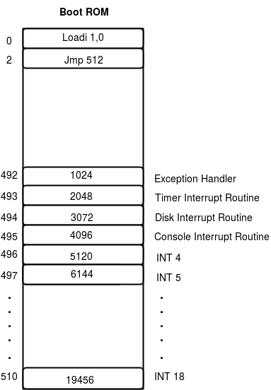
INT 4 to INT 18 instructions are called software interrupts or traps. The XSM machine has an interrupt vector table that maps each interrupt number to a corresponding address (of the interrupt handler). The vector table is stored starting from physical address 492 of memory. Locations 492,493,494 and 495 stores the addresses of the exception handler, the timer interrupt handler, the disk interrupt handler and console interrupt handler. Location 496 contains the address of the first trap handler - INT 4, location 497 contains the address of INT 5 handler and so on. When the machine encounters an INT n instruction, the corresponding ROM location is searched for the handler address, and IP is set to this value. Since the values are hard-coded in the ROM code of the XSM simulator given to you, you cannot change the addresses of the handlers.
Why do you need software interrupts?
As explained previously, application programs run in unprivileged mode and cannot access memory beyond its virtual address space. If the application wishes to do tasks like input-output or disk access which are not permitted in unprivileged mode, then the OS must provide a "regulated access mechanism" through which the application can invoke an OS routine to do the task. The OS routine must be designed to run in privileged mode, must validate the application's request (permissions, etc.), perform the task and then return to the application.
OS handlers that can be called from application programs for privileged tasks are known as system call routines. Software interrupts provide hardware support mechanism for implementing system calls. In the eXpOS project, the mapping of each system call to interrupt numbers is given here. (Note that in some cases, the same interrupt handler is designed to handle multiple system calls. In such cases the system call number passed as an argument to the interrupt handler is used to identify the correct service).
Typically, the application pushes the input arguments to a system call handler into the
stack before executing INT instruction. The handler after doing the corresponding action
stores return value in a designated position in the application's stack. The conventions
regarding how arguments and return values are passed are stipulated in the ABI.
Example: In our running example, suppose the instruction at logical address 2070 is INT 4:
0
2056
0
0
0
0
0
0
MOV R0, 1
MOV R1, 0
CMP R0, 10
JNZ 2070
ADD R1, R0
ADD R0, 1
JMP 2060
INT 4
The INT 4 instruction will push the logical address of the next instruction (2072) into the physical location corresponding to the top of the stack (SP contains logical address of the top of the stack). The INT instruction then sets IP register to address 5120 by refering to the vector table and changes the machine mode to privileged. Hence, the next instruction will be fetched from 5120. Later when the interrupt handler executes an IRET instruction, the IP value (2072) to be popped off the stack so that execution continues with the instruction at logical address 2072. (Note that the above description had assumed that the INT handler has not changed the value of PTBR. What would happen if PTBR is changed?)
Note: In the eXpOS project, you will have to write code for various trap handlers and store it on
the disk. Your bootstrap loader must load these interrupt handlers from the disk to the appropriate memory
pages. The eXpOS system has clear specification regarding the disk locations where each interrupt handler
must be stored and the memory pages to which the OS bootstrap loader must place each interrupt handler.
This is specified in the eXpOS Memory Organisation documentation.
This completes our discussion on XSM unprivileged execution mode.