XSM Instruction Execution Cycle
This tutorial will help you to understand the architectural features of the XSM machine necessary to for implementing the eXpOS operating system. These features will be used by the eXpOS kernel.
The CPU of the XSM machine contains 20 general-purpose registers R0-R19, each of which can store an integer or a string. (see XSM specification). Along with these are the registers stack pointer (SP), base pointer (BP) and instruction pointer (IP). There are other special purpose registers: PTBR, PTLR, EIP, EC, EPN, EMA and four ports P0, P1, P2, P3. We will discuss the roles of these soon.
The machine's memory consists of 65536 memory words. Each word can store an integer or a string. The memory is divided into pages of 512 words each. Thus memory addresses 0 to 511 belong to page 0, 512-1023 belong to page 1 and so on. The last (page 127) contain memory addresses 65024 to 65535. The memory is word addressable. This means that XSM provides instructions that allows you to access any memory word. For instance, the instruction "MOV R0, [1345]" transfers the contents of memory location 1345 to register R0.
The machine also has a disk having 512 blocks. Each disk block can store 512 words. Thus the total storage capacity is 512 x 512 = 262144 words. However, the disk is block addressable and not word addressable. XSM provides just three instructions to manipulate the disk – LOAD, LOADI and STORE. These instructions can be used to transfer a disk block to a memory page or back. Suppose we want to access the 10th word of block 12, then the only way to do so is to first transfer the 12th block to some memory page and then access the corresponding memory address.
Apart from disk and memory, the machine also has three devices – an I/O Console, a timer and disk controller. We will discuss them later. The organisation of the XSM machine is given here
The machine can operate in two fundamental modes of execution – privileged and unprivileged. When the machine gets powered on, it begins execution in the privileged mode. We will discuss unprivileged mode later and assume privileged mode execution in the following.
Note
The ExpOS documentation (unfortunately) uses the words "kernel mode" for privileged mode and "user mode" for unprivileged mode execution. This terminology arose because the OS kernel code runs in privileged mode and application programs run in unprivileged mode. However "kernel" and "user" are OS level abstractions, not connected to the machine, and the terminology is not used in this document while referring to architectural concepts.
Boot-up
What happens when the machine is powered on?
All registers will be set to value zero. In particular, IP register also assumes value 0. Once powered on, the machine will start repeatedly executing the following fetch-execute cycle in privileged mode.
- Transfer the contents of two memory locations starting at the address stored in IP register to the CPU. The XSM machine treats the contents read like a machine instruction. This action is called the instruction fetch cycle.
- The next step is the execute cycle where the instruction fetched in Step 1 is executed by the machine. What happens here depends on the instruction. (See XSM instruction set.) For example, if the instruction fetched is "MOV R0, [1256]", the execute cycle action will result in the contents of memory location 1256 being transferred to register R0. If the instruction fetched is "JMP 1110", the value of the IP register will be set to 1110.
- The final step is to set the instruction pointer to the next instruction to be executed. Since each XSM instruction is two words, IP will normally be incremented by 2. There are exceptions to this rule. For instance in the case of "JMP 1110", IP is set to 1110 and hence not incremented. Thus the next fetch must be from 1110. After Step 3, the machine loops back to Step 1.
Also see Wiki Link.
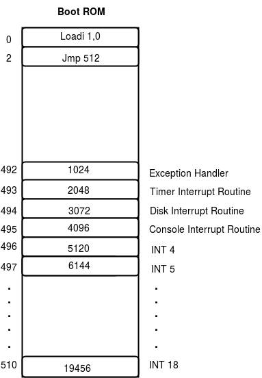
When the machine is just powered on, IP value is 0. Hence, the first instruction will be fetched from memory locations 0 and 1. The XSM machine has a boot ROM containing just two instructions:
| Location | Instruction | Instruction semantics |
|---|---|---|
| 0 | LOADI 1, 0 | Load contents of disk block 0 to memory page 1 |
| 2 | JMP 512 | Change IP value to 512 |
The bootstrap code is hard coded into a boot ROM so that the memory contents are not lost even after machine shutdown. This is necessary because when the machine is powered on, there must be some meaningful instruction at address 0 from where the first fetch takes place.
Study the above bootstrap code carefully. What it does is to load the contents of disk block 0 to memory page 1 and then set the IP value to 512 so that the next fetch happens from memory address 512. This last step is very important because the machine will fetch contents of memory address 512 and 513 next, decode it assuming there is a valid instruction stored there and execute it and proceed from there. Hence, if you write an XSM assembly language program and store it in block 0 in such a way that your first instruction is stored in the first word of block 0, the machine will execute it immediately after JMP 512. Consequently, your code gets control of the machine, and the fetch-execute cycle continues with your code. You will be writing the OS bootstrap loader and storing it in block 0 in Stage 3 of the eXpOS roadmap.
Note
The boot ROM actually contains more information than what is written above. The boot ROM contains an interrupt vector table located between addresses 492 to 511. The vector table specifies the physical address to which interrupts must transfer control to. Locations 492,493,494 and 495 stores the addresses of exception handler, timer interrupt handler, disk interrupt handler and console interrupt handler. Location 496 contains the address of the first trap handler - INT 4, location 497 contains address of INT 5 handler and so on. When the machine encounters an INT n instruction, the corresponding ROM location is searched for the handler address and IP is set to this value. Note that the interrupt vector table is hard-coded in the ROM code of the XSM simulator given to you, you cannot change the addresses of the handlers. The figure below gives the layout of Boot ROM.
Privileged mode of execution
The privileged mode of execution is easy to comprehend. All instructions in the XSM machine instruction set described here will execute in the most natural way in the privileged mode of execution. Most of the instructions like data transfer instructions, arithmetic and logic instructions, and control flow instructions (JMP etc.) are straightforward to understand from the specification and not described here.
Instead, we will focus here on the execution semantics of the following four (slightly non-trivial) instructions when executed in privileged mode – PUSH, POP, CALL and RET.
The value of the SP register holds a pivotal role in these operations.
The PUSH instruction results in the following actions:
- Contents of SP gets incremented by 1.
- The data specified by the PUSH instruction is transferred to the location pointed to by SP.
- IP gets incremented by 2 to point to the next instruction.
Example:
MOV SP, 1000   //  SP register is loaded with value 1000.
PUSH R0    //  SP is set to 1001 and contents of R0 is copied to memory address 1001.
The POP instruction is a reverse operation to PUSH. The contents of the memory address pointed to by SP will be retrieved to a register specified, and SP is decremented.
The CALL instruction results in the following:
- Increment SP by one.
- Transfer contents of IP register + 2 to the memory address pointed to by SP.
- Set IP to the value of register/constant value specified in the CALL instruction.
Example:
MOV SP, 1000  //  SP is set 1000
CALL 21110   //  a) Increment SP to1001, b) Copy contents of IP to location 1001 c) MOV 21110 to IP register.
The RET instruction reverses the actions of a CALL instruction. The contents of address pointed to by SP register is copied to the IP register, and SP is decremented. Since IP is modified, the next instruction is fetched from the newly set value.
Finally, we initiate a discussion on the most complicated instruction – IRET. This instruction can be only executed in privileged mode, but IRET is the only XSM instruction that results in the XSM machine to switch from the privileged mode to unprivileged mode. After an instruction fetch, if the XSM encounters the IRET instruction, the following actions take place:
- Enable paging and change from privileged mode to unprivileged mode
- Execute the RET instruction in the unprivileged mode. (The execution semantics now is different, and you must read XSM unpriviliged mode execution to understand how RET works in unprivileged mode).
After the IRET instruction, the machine continues fetch-execute cycle, but in the unprivileged mode. Note that the change of machine mode from privileged to unprivileged happens before the actual fetch-execution cycle. Thus, to understand how an instruction works, one needs to know how paging and address translation works.