Machine Organisation
Processor
The processor consists of a set of registers and ports along with the hardware for performing control and arithmetic/logic operations, paging etc. Each register/port can store a string.
The machine is equipped with an instruction set. Two contiguous memory words are necessary to store each XSM instruction. The reader is assumed to have a basic understanding of the general principles of computer organization, hardware and software interrupts, exceptions, and hardware paging to follow the processor description in this document.
The processor has two fundamental modes of operation - privileged execution mode and the unprivileged execution mode. A program executing in the privileged mode can execute any XSM instruction and has the full view of the memory and the disk. A program executing in the unprivileged mode has access only to a restricted machine model called the XSM virtual machine. The instruction set and the memory model available to a program executing in unprivileged mode is a subset of that in the privileged mode. These are called the virtual machine instruction set and the virtual machine memory model respectively. ( See Virtual Machine Specification for more). XSM implements the virtual machine model using its paging hardware.
XSM Machine Registers/Ports
The XSM architecture maintains 29 registers, each capable of storing a word. Only a few of them are accessible in unprivileged mode. Several registers are special purpose registers reserved for specific purposes. The machine also contains 4 ports, of which one port is used for Standard Input and another one is used for Standard Output. The remaining ports are unused in the present version of XSM.
The following table gives an overview of XSM registers/ports according to their category.
| Registers | Purpose | Access Mode |
|---|---|---|
| *R0-R19 | General Purpose User Registers | Unprivileged |
| BP, SP, IP | Base, Stack and Instruction Pointers | Unprivileged |
| PTBR, PTLR | Page Table (Base, Length) Registers | Privileged |
| EIP, EC, EPN, EMA | Exception Status Registers | Privileged |
| P0-P3 (Ports) | P0-Input port, P1-Output port P2,P3-Unused | Privileged |
* The registers R12 - R15 (both inclusive) must be used by the system programmer with caution as they may be used by the OS.
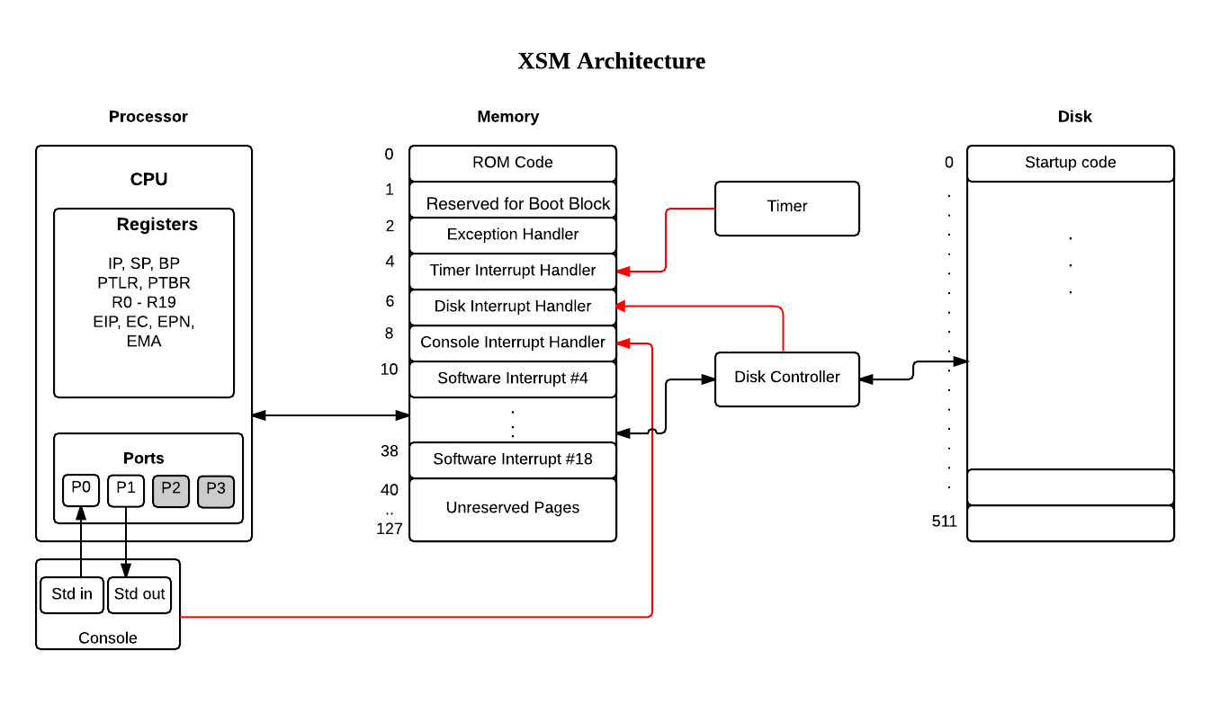
Memory
Memory refers to the physical memory of the machine and is a volatile storage. The memory is organized as a sequence of pages. Each page is a sequence of 512 words. The total number of memory pages available is 128. Thus there are in total 512 x 128 = 65536 words of storage. The memory is word addressable. The machine contains data transfer instructions that allow a word to be transferred from memory to a register/port and back.
When the machine is executing in privileged mode, a memory address “N” between 0 and 65535 refers to the word with offset (N mod 512) in page number (N div 512).
Note
Since the memory model is different when the machine operates in unprivileged mode, the total amount of memory and the interpretation of addresses are different and will be discussed in the Virtual Machine Specification.
The Memory of the XSM Machine is organised as follows :
| Page Number | Contents | Word Address | Number of Words |
|---|---|---|---|
| 0 | ROM Code | 0 - 511 | 512 |
| 1 | Page for loading the BOOT block | 512 - 1023 | 512 |
| 2 - 3 | Exception handler (INT 0) | 1024 - 2047 | 1024 |
| 4 - 5 | Timer Interrupt (INT 1) | 2048 - 3071 | 1024 |
| 6 - 7 | Disk Interrupt (INT 2) | 3072 – 4095 | 1024 |
| 8 - 9 | Console Interrupt (INT 3) | 4096 – 5119 | 1024 |
| 10 - 11 | INT 4 (Create, Delete) | 5120 - 6143 | 1024 |
| 12 - 13 | INT 5 (Seek, Open, Close) | 6144 - 7167 | 1024 |
| 14 - 15 | INT 6 (Read) | 7168 - 8191 | 1024 |
| 16 - 17 | INT 7 (Write) | 8192 - 9215 | 1024 |
| 18 - 19 | INT 8 (Fork) | 9216 - 10239 | 1024 |
| 20 - 21 | INT 9 (Exec) | 10240 - 11263 | 1024 |
| 22 - 23 | INT 10 (Exit) | 11264 - 12287 | 1024 |
| 24 - 25 | INT 11 (Getpid, Getppid, Wait, Signal) | 12288 - 13311 | 1024 |
| 26 - 27 | INT 12 (Logout) | 13312 - 14335 | 1024 |
| 28 - 29 | INT 13 (Semget, Semrelease) | 14336 - 15359 | 1024 |
| 30 - 31 | INT 14 (SemLock, SemUnLock) | 15360 - 16383 | 1024 |
| 32 - 33 | INT 15 (Shutdown) | 16384 - 17407 | 1024 |
| 34 - 35 | INT 16 (Newusr, Remusr, Setpwd, Getuname, Getuid) | 17408 - 18431 | 1024 |
| 36 - 37 | INT 17 (Login) | 18432 - 19455 | 1024 |
| 38 - 39 | INT 18 (Test0, Test1, Test2, Test3) | 19456 - 20479 | 1024 |
| 40 - 127 | Unreserved Pages | 20480 - 65535 | 45056 |
Note
The last 19 words of page 0 are reserved for an interrupt vector table with 19 entries. The kth entry contains the page number where the handler for the kth interrupt service routine begins. Upon encountering the INT k instruction during machine execution, the machine transfers control to the beginning of the page indicated in the corresponding vector table entry.
The version of the XSM machine described here assumes that the vector table entries are hard coded in the ROM code according to the above table.
Disk
The disk is organized as a sequence of 512 blocks. Each block is a sequence of 512 words. Thus there are a total of 512x512=262144 words of secondary storage.
The disk is block accessible and not word accessible. This means that a word within a block can be accessed individually only after transferring the block into memory and then accessing the corresponding word from the memory.
A block index between 0 and 511 refers to the corresponding disk block.
The block 0 of the disk is reserved for boot block and will be loaded into the memory at the time of system startup.
The machine instruction set includes four special disk access macro routines (load, loadi and store - see instruction set ) for disk-block to memory-page data transfer and back. These are actually macros whose internal details are hidden from programs. These macros are accessible only when the machine is executing in privileged mode. XSM gives no provision for programs to access the disk directly while executing in unprivileged mode.
Note
The fact that both page-size and block-size are the same makes disk to memory transfer easy in XSM. In real machines, this is normally not the case and the disk access routines have to do the necessary size mappings.
Timer
Timer is a device that can be set to interrupt the processor each time after the machine executes XSM_TICKS instructions in unprivileged mode (If the XSM_TICKS numbered instruction changes mode from unprivileged to privileged, then the interrupt occurs before executing the next instruction after the machine is back to unprivileged mode). The value of XSM_TICKS must be set externally. (XSM specification leaves how XSM_TICKS is initialized to the implementation.) Upon receipt of the interrupt, the machine switches to the privileged mode and executes the timer interrupt service routine.
Disk Controller
Disk Controller is the device that controls the data transfer between the memory and the disk. If the load macro or store macro is used for disk-memory transfer, then upon subsequent completion of XSM_DTIME instructions in the unprivileged mode, the disk controller interrupts the machine. (If the XSM_DTIME numbered instruction changes mode from unprivileged to privileged, then the interrupt occurs before executing the next instruction after the machine is back to unprivileged mode). Upon receipt of the interrupt, the machine executes disk interrupt service routine. If the loadi macro is used for disk-memory transfer, the machine will wait for the block transfer and will continue the execution of next instruction only after the block transfer is complete.
Console/Terminal
The console device is a single device that handles the standard input and output.
The OUT instruction displays the contents of port P1 onto the terminal (see instruction set).
If the XSM machine executes an IN instruction, the console device waits for the user to enter a word into the console. When a word is entered, the console device transfers the word to the port P0 and raises the console interrupt (see console interrupt handling). The console device ignores any further input entered by the user before the execution of another IN/INI instruction. While the console waits for the user input, the XSM machine proceeds the execution of the next instruction.
If the XSM machine executes the INI instruction (which can be used only in debug mode), the console device as well as the XSM machine waits for the user input and the data entered is immediately transferred to the port P0, only after which the next instruction is executed. No interrupt is generated by the INI instruction.
The contents of port P0 may be transfered to other registers/memory using the MOV instruction inside the console interrupt routine. Note that P0 will contain valid data only after the console has sent an interrupt for the IN instruction.
Boot ROM and Boot block
When XSM machine starts up, program execution starts at the first word of the first page (Page 0) of memory. There is a pre-loaded ROM code in Page 0 called the bootstrap loader. This code loads the 1st disk block (block 0) called the boot block from the disk to page 1 of memory and then transfers control (using the jump instruction) to the 1st instruction in page 1. This mechanism allows programmers to write their code and store it in the boot block so that when the machine starts up, control is transferred to this code.
The XSM machine has an interrupt vector table that maps each interrupt number to a corresponding address (of the interrupt handler). The vector table is stored starting from physical address 492 of memory. Locations 492,493,494 and 495 stores the addresses of exception handler, timer interrupt handler, disk interrupt handler and console interrupt handler. Location 496 contains the address of the first trap handler - INT 4, location 497 contains address of INT 5 handler and so on. When the machine encounters an INT n instruction, the corresponding ROM location is searched for the handler address and IP is set to this value.
Note that the interrupt vector table is hard-coded in the ROM code of the XSM simulator given to you, you cannot change the addresses of the handlers.
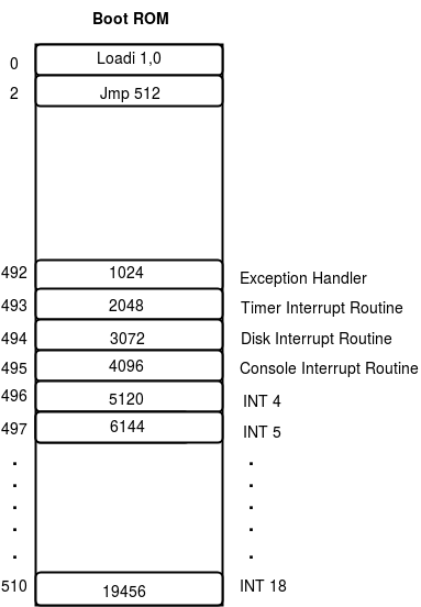
Note
Boot ROM code contains just 2 instructions (to load the Boot Block to page 1 and then jump to page 1 which now contains Boot Block). So, after the execution of Boot ROM, control is transferred to 1st instruction in page 1.